Vacuum furnace quenching oil cooling system used for thermal treatment

A technology of cooling system and quenching oil, which is applied in heat treatment equipment, heat treatment process control, quenching device, etc., can solve the problems that it is difficult to meet the requirements of rapid cooling of quenching oil and the uniformity of quenching oil cooling, and achieve flexible cooling speed, The effect of adjusting the cooling rate

Active Publication Date: 2017-07-21
江苏石川岛丰东真空技术有限公司
View PDF7 Cites 2 Cited by
  • Summary
  • Abstract
  • Description
  • Claims
  • Application Information

AI Technical Summary

Problems solved by technology

The existing external vacuum furnace quenching oil cooling system for heat treatment has the following obvious defects: it is difficult to meet the requirements of uniformity of quenching oil cooling, and it is difficult to achieve the requirements of rapid cooling of quenching oil

Method used


Image

  • Vacuum furnace quenching oil cooling system used for thermal treatment
  • Vacuum furnace quenching oil cooling system used for thermal treatment

Examples


Embodiment Construction

[0014] In order to make the above objects, features and advantages of the present invention more comprehensible, the present invention will be further described in detail below in conjunction with the accompanying drawings and specific embodiments.

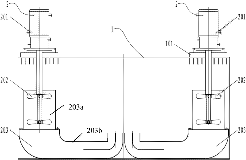
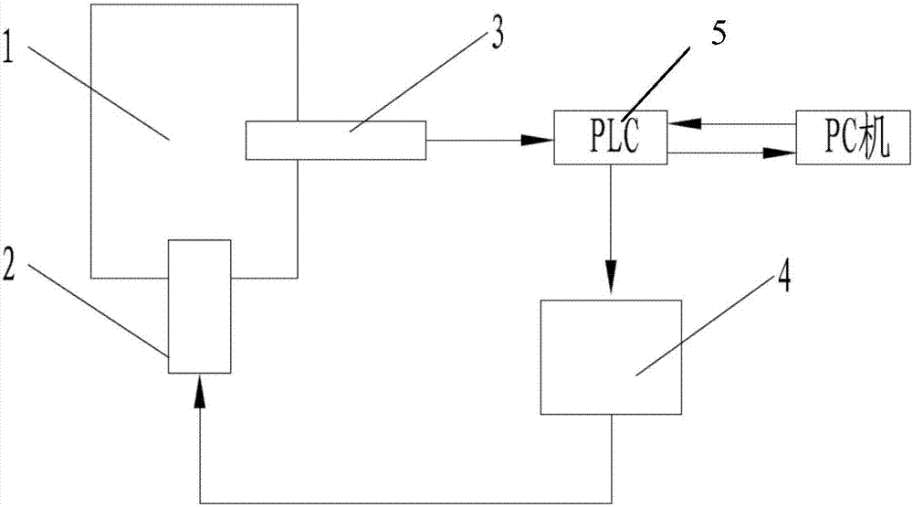
[0015] like figure 1 and figure 2 As shown, in a specific embodiment, the vacuum furnace quenching oil cooling system for heat treatment provided by the present invention includes a quenching oil tank 1, a quenching oil stirring and lifting device 2 and other components.

[0016] Water-cooled walls 101 are laid on the left and right ends of the top wall of the quenching oil tank 1 , and water circulation pipes are installed in the water-cooled walls 101 , and the water-cooled walls 101 can exchange heat with the external environment.

[0017] In this embodiment, two sets of quenching oil stirring and lifting devices 2 are provided, which are respectively arranged at the positions of two water-cooled walls 101. Each group of quen...


PUM


Abstract

The invention provides a vacuum furnace quenching oil cooling system used for thermal treatment. The vacuum furnace quenching oil cooling system comprises a quenching oil tank. A water cooling wall and multiple sets of quenching oil stirring and lifting devices penetrating the water cooling wall are arranged on the top wall of the quenching oil tank. The quenching oil stirring and lifting devices extend into the quenching oil tank downwards and are used for lifting quenching oil in the quenching oil tank to the position of the water cooling wall so that the quenching oil can be cooled. Compared with the prior art, the vacuum furnace quenching oil cooling system has the following remarkable technical effects that it is ensured that the quenching oil in the quenching oil tank is uniformly cooled, the stirring speed of stirrers can be flexibly controlled, and therefore the cooling speed of the quenching oil is flexibly regulated.

Description

technical field [0001] The invention relates to a heat treatment device, in particular to a vacuum furnace quenching oil cooling system for heat treatment. Background technique [0002] Vacuum furnace is regarded as one of the equipments for upgrading equipment in the heat treatment industry. The important reason is that the product parts processed by vacuum furnace have bright surface, less oxidation, good performance and high precision. It is easy to realize energy saving, consumption reduction and reduction in the production and operation of vacuum furnace. It belongs to clean production equipment and meets the requirements of today's environmental protection. There are very few gas molecules in vacuum, and the free path of molecules becomes larger, so light rare metals, refractory metals, rare metals and other special alloy materials that cannot be obtained under normal pressure can be produced. [0003] In the prior art, the quenching oil cooling system of the vacuum f...

Claims


Application Information

Patent Timeline
Patent Type & Authority Applications(China)
IPC IPC(8): C21D1/64C21D11/00
CPCC21D1/64C21D11/005
Inventor 杨晔朱楼飞袁建锋
Owner 江苏石川岛丰东真空技术有限公司
Why Eureka
Try Eureka