Switchable cloth dyeing and printing equipment

A printing and dyeing equipment, switchable technology, applied in the field of switchable cloth printing and dyeing equipment, can solve the problems of self-adjustment, flexible switching of different color dyeing boxes, etc., and achieve the effect of convenient positioning

Inactive Publication Date: 2017-07-21
CHANGXING JIAPU YIHANG TEXTILE FACTORY
View PDF1 Cites 4 Cited by
  • Summary
  • Abstract
  • Description
  • Claims
  • Application Information

AI Technical Summary

Problems solved by technology

[0006] The purpose of the present invention is to overcome the shortcomings of the prior art and overcome the problems that the equipment does not have the flexibility to switch dyeing boxes of different colors and the self-adjustment of the amount of dye injection

Method used


Image

  • Switchable cloth dyeing and printing equipment
  • Switchable cloth dyeing and printing equipment
  • Switchable cloth dyeing and printing equipment

Examples


Embodiment 1

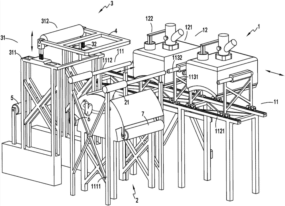
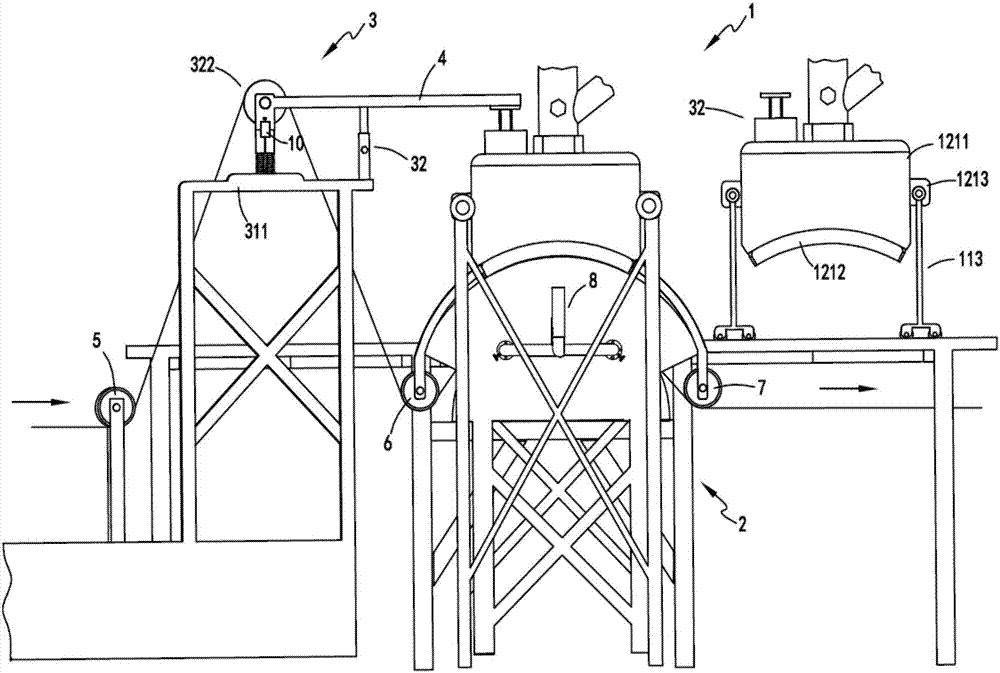
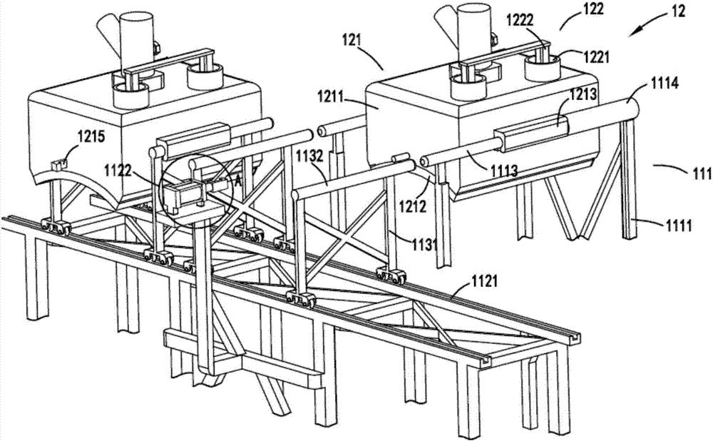
[0048] figure 1 It is a schematic diagram of the switchable cloth printing and dyeing equipment, figure 2 It is a schematic diagram of the front view of the switchable cloth printing and dyeing equipment, image 3 It is a schematic diagram of the switching mechanism and the spraying mechanism, Figure 4 Schematic diagram of the enlarged structure of the positioning push-pull device, Figure 5 It is a schematic diagram of the structure of the spraying device when it is transferred from the walking support unit to the spraying support unit, Figure 6 Schematic diagram of the structure of the regulation part, Figure 7 It is an enlarged schematic diagram of part of the structure of the lifting device, Figure 8 It is a structural schematic diagram of the wrinkle removal unit and the absorption unit, Figure 9 is a cutaway schematic diagram of the wrinkle removal unit, Figure 10 A cutaway schematic diagram of the spraying device, Figure 11 It is a cutaway schematic diagram...

Embodiment 2

[0066] Such as figure 1 , figure 2 , image 3 , Figure 4 , Figure 5 , Figure 6 , Figure 7 , Figure 8 , Figure 9 , Figure 10 and Figure 11 As shown, the components that are the same as or corresponding to those in the first embodiment are marked with the corresponding reference numerals in the first embodiment. For the sake of simplicity, only the differences from the first embodiment will be described below. The difference between the second embodiment and the first embodiment is that a sliding locking device 32 for locking the height of the lifting device 312 and the pressure regulating plug 1222 is provided between the lifting mechanism 31 and the pressure regulating device 122 One end of the sliding locking device 32 is fixed on the frame 311 and the other end is fixed on the fixed frame 4 .

[0067] In order to ensure that the pressure regulating plug 1222 will not slide up and down during the cloth transmission process after the adjustment is completed,...

Embodiment 3

[0069] Such as figure 1 , figure 2 , image 3 , Figure 4 , Figure 5 , Figure 6 , Figure 7 , Figure 8 , Figure 9 , Figure 10 and Figure 11As shown, the parts that are the same as or corresponding to those in the second embodiment are marked with the corresponding reference numerals in the second embodiment. For the sake of simplicity, only the differences from the second embodiment will be described below. The difference between the third embodiment and the second embodiment is that the outer port of the wrinkle removal hole 232 on the left side is inclined toward the center position on the corresponding arc surface with the center position as the dividing line of the negative pressure chamber a231, and the outer port on the right side is inclined toward the center position. The outer port of the corrugation hole 232 is also inclined towards the central position.

[0070] The negative pressure chamber a231 and the wrinkle removal hole 232 are set in the wrink...


PUM


Abstract

The invention relates to a switchable cloth printing and dyeing equipment, which includes a dyeing box part, the dyeing box part includes a switching mechanism and a spraying mechanism; the switching mechanism includes a spraying support unit, a switching unit and a walking support unit; the spraying mechanism includes a spraying mechanism device and a pressure regulating device arranged on the spraying device; the spraying part, the spraying part is arranged below the spraying support unit, the spraying part includes a spraying station, and a support is arranged below the spraying station , the front end of the support is provided with a wrinkle removal unit, and the rear end of the support is provided with an absorption unit; the adjustment part, the adjustment part is arranged above the spraying mechanism, and the adjustment part includes a lifting mechanism that moves up and down under the action of gravity of the cloth, and the lifting mechanism Cooperate with the spraying mechanism on the spraying station to drive the pressure regulating device on the spraying mechanism to adjust the pressure inside the spraying device; it overcomes the problem that the equipment does not have the flexibility to switch different color dyeing boxes and does not have the ability to self-adjust the amount of dye injection question.

Description

technical field [0001] The invention relates to the technical field of textile printing and dyeing equipment, in particular to a switchable cloth printing and dyeing equipment. Background technique [0002] There are generally two types of fabric dyeing techniques, painting and dip-dyeing. Exhaust dyeing method pollutes a lot and wastes materials. For painting and dyeing, the existing painting and dyeing equipment has the problems of single equipment structure, one set of equipment can only be used for one color cloth spraying and the spraying effect is not stable. [0003] A Chinese utility model patent with the authorized announcement number CN203782393U discloses a high-efficiency small bath ratio open-width spray dyeing machine. Water-based; however, the device has the following problems: [0004] 1. The equipment has a single structure and does not have the function of flexible switching. The dyeing box cannot be cleaned, so it only meets the use of one color. [000...

Claims


Application Information

Patent Timeline
Patent Type & Authority Applications(China)
IPC IPC(8): D06B1/02D06B23/00D06B23/20D06B23/24
CPCD06B1/02D06B23/00D06B23/20D06B23/24
Inventor 嵅奇
Owner CHANGXING JIAPU YIHANG TEXTILE FACTORY
Why Eureka
Try Eureka