Water energy storage system with multiple units connected in series and use method thereof

A technology of water energy storage and multiple units, applied in the field of energy storage, can solve the problems of high construction cost, high operation cost, poor energy storage efficiency, etc., and achieve the effects of reducing construction cost, good stratification effect, and reducing operating electricity.

Active Publication Date: 2017-07-21
SHENZHEN DAS INTELLITECH CO LTD
View PDF6 Cites 1 Cited by
  • Summary
  • Abstract
  • Description
  • Claims
  • Application Information

AI Technical Summary

Problems solved by technology

[0006] The purpose of the present invention is to provide a water energy storage system with multiple units in series and its use method, which solves the problems of high construction cost, poor energy storage efficiency, and high operating cost of the energy storage system in the prior art

Method used


Image

  • Water energy storage system with multiple units connected in series and use method thereof
  • Water energy storage system with multiple units connected in series and use method thereof

Examples


Embodiment 1

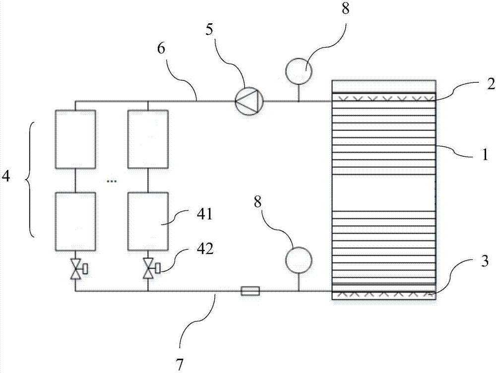
[0025] Such as figure 1 As shown, the water storage tank 1 is connected in parallel with a plurality of water temperature conversion machine assemblies 4 through the upper water distributor 2 and the lower water distributor 3, and each water temperature conversion assembly 4 includes two groups of water temperature conversion machines connected in series, each group of water temperature conversion machines The quantity of the water temperature conversion machine 41 is one. That is to say, the water temperature conversion machines 41 are first connected in series, and then connected in parallel.

Embodiment 2

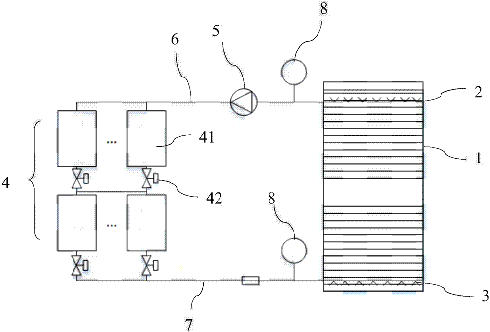
[0027] Such as figure 2 As shown, the water storage tank 1 is connected in parallel with a water temperature converter assembly 4 through the upper water distributor 2 and the lower water distributor 3. The water temperature conversion assembly 4 includes two sets of water temperature converters connected in series, and the water temperature in each group of water temperature converters is There are multiple converters 41 connected in parallel. That is to say, the water temperature conversion machines 41 are firstly connected in parallel, and then connected in series.

[0028] Such as Figure 1-2 As shown, the outlet pipe of the water temperature conversion machine 41 is provided with an electric valve 42, and the cold storage water pump 5 is provided with a speed regulating device (not shown in the figure), and the electric valve 42 and the speed regulating device are respectively connected to the controller through a data line (in the figure not marked).

[0029] A high-...


PUM


Abstract

The invention relates to a water energy storage system with multiple units connected in series and a use method of the water energy storage system with the multiple units connected in series. The water energy storage system with the multiple units connected in series comprises a water storage tank. The upper portion and the lower portion of the water storage tank are provided with an upper water distributer and a lower water distributer correspondingly. The water storage tank is connected with at least one water temperature converter assembly through the upper water distributer and the lower water distributer. A cold storage water pump is arranged between the upper water distributer and the water temperature converter assemblies. Each water temperature converter assembly comprises at least two groups of water temperature converters connected in series. By the adoption of the water energy storage system with the multiple units connected in series, the temperature difference between high-temperature water and low-temperature water can be increased, and the energy storage amount of water of unit volume can be increased; under the condition of the same energy storage amount, the volume of the water storage tank is reduced, the number of the cold storage water pump or the flow of the cold storage water pump is reduced, and the construction cost is reduced; because the flow the cold storage water pump or the number of the cold storage water pump is reduced, under the condition of the same cold storage amount, the operation electricity of the cold storage water pump is reduced, the layering effect is better, and the energy storage efficiency is higher.

Description

technical field [0001] The invention relates to the technical field of energy storage, and more specifically relates to a water energy storage system with multiple units connected in series and a method for using the same. Background technique [0002] At present, most regions of the country implement the policy of peak and valley electricity prices (peak electricity price, flat electricity price and valley electricity price), that is, different electricity unit prices are implemented at different times to guide users to reasonably adjust electricity loads and achieve effective allocation of power resources. The central air-conditioning system has been widely used in industrial and civil fields. It is usually composed of chiller or hot water unit, chilled water pump or hot water pump, cooling water pump, cooling tower, air conditioning terminal, valves and connecting pipelines, etc., to achieve cooling or heating. production, transportation, exchange and adjustment to meet t...

Claims


Application Information

Patent Timeline
Patent Type & Authority Applications(China)
IPC IPC(8): F24F5/00F24F11/02F24F11/00F24F13/30
CPCF24F5/0017F24F11/30F24F13/30F24F2110/00Y02E60/14
Inventor 李信洪谢辉优薛新峰
Owner SHENZHEN DAS INTELLITECH CO LTD
Why Eureka
Try Eureka