
Encoder and installation method thereof

An encoder and grating technology, which is applied in the field of encoder structure design, can solve problems such as poor reliability of the encoder, and achieve the effects of improving installation efficiency, good protection, and reducing processing costs

Inactive Publication Date: 2017-07-21
SHANGHAI LEIZHI MOTOR
View PDF10 Cites 5 Cited by
  • Summary
  • Abstract
  • Description
  • Claims
  • Application Information

AI Technical Summary

Problems solved by technology

[0010] One of the main purposes of the present invention is to provide an encoder with high reliability, good versatility, convenient installation and high installation efficiency, which solves the problem of poor reliability of the encoder caused by bearing reliability

Method used


Image

  • Encoder and installation method thereof
  • Encoder and installation method thereof

Examples


Embodiment

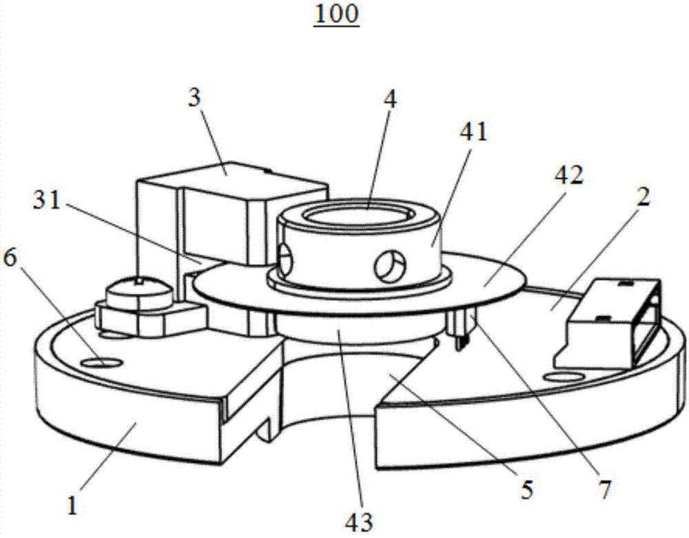
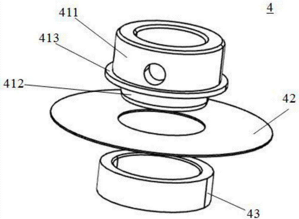
[0038] Please refer to Figure 1-Figure 2 , the present embodiment is an encoder 100, which includes an encoder bracket 1, a PCB circuit board 2 embedded in the encoder bracket 1, a reading head 3 electrically connected to the PCB circuit board 2, and a motor rotating The rotating assembly 4 on the shaft, the rotating assembly 4 is assembled by the grating bracket 41, the grating 42 and the multi-pole magnetic ring 43, the multi-pole magnetic ring 43 is sleeved on the lower end of the grating bracket 41, and the grating 42 is sleeved on the grating bracket 41 and located between the grating support 41 and the multi-pole magnetic ring 43 .

[0039] The side surface of the reading head 3 is provided with a groove 31 for accommodating the grating 42. The grating 42 rotates together with the motor shaft. Whenever the grating 42 passes through the groove 31, the reading head 3 records, thereby controlling the rotation of the motor.

[0040] The encoder bracket 1 and the PCB circui...


PUM


Abstract

The invention discloses an encoder and an installation method thereof. The encoder comprises an encoder support, a PCB embedded in the encoder support, a number reading head electrically connected to the PCB and a rotation assembly sleeving a rotation shaft of a motor. The rotation assembly is formed by assembling an optical grating support, an optical grating and a multi-pole magnetic ring. The multi-pole magnetic ring sleeves the lower end of the optical grating support. The optical grating sleeves the optical grating support and is arranged between the optical grating support and the multi-pole magnetic ring. U-type openings penetrating through the encoder support and the surface of the PCB are arranged in the same positions of the encoder support and the PCB. According to the invention, the encoder is highly reliable and universal, convenient to install and high in installation efficiency, so problem of poor reliability of the encoder caused by a reliability reason of the bearing is solved.

Description

[0001] 【Technical field】 [0002] The invention belongs to the technical field of encoder structure design, and in particular relates to an encoder and an installation method thereof. [0003] 【Background technique】 [0004] With the development of science and technology and industrial automation, automatic control technology has been applied more and more in various fields. The servo system with the servo motor as the control object has gradually penetrated into all aspects of industrial production, scientific research and national defense. Various equipment (such as industrial robots, CNC machine tools and aerospace equipment, etc.) have higher and higher requirements for servo systems, such as: short response time, high stability of rotational speed and torque, and high positioning accuracy. One of the core factors for the servo system to meet the above high requirements is that the encoder installed on the servo motor should have high resolution, high precision and good op...

Claims


Application Information

Patent Timeline
Patent Type & Authority Applications(China)
IPC IPC(8): G01D5/14
CPCG01D5/142
Inventor 荆红民张晨徐军
Owner SHANGHAI LEIZHI MOTOR
Learn More