
Loading test apparatus for simulating ship thruster

A loading test device and technology of loading device, applied in the testing of machine/structural components, measuring device, testing of mechanical components, etc., can solve the problem of not considering the influence of torque load vibration, reducing the reliability of the test bench, and dimensionally unstable flow field Restrictions and other issues to achieve the effect of eliminating the impact

Active Publication Date: 2017-07-21
CHINA SHIP SCIENTIFIC RESEARCH CENTER (THE 702 INSTITUTE OF CHINA SHIPBUILDING INDUSTRY CORPORATION)
View PDF12 Cites 15 Cited by
  • Summary
  • Abstract
  • Description
  • Claims
  • Application Information

AI Technical Summary

Problems solved by technology

For example, Zhu Hanhua of Wuhan University of Technology proposed a shafting electromagnetic-hydraulic comprehensive simulation test loading device (CN 104807629A). A DC electromagnetic torque device is used for torque loading at the middle section of the test shaft, and a hydraulic method is used for axial force loading at the stern end of the shaft. , and radial force loading in multiple directions can also be carried out at the same time, but this device is mainly used for performing performance tests and ultimate load destructive tests on the shafting before installation, and at the same time, it uses ball bearings to connect When introducing additional pulsating force influence; a simulated ship propulsion control system (invention patent: CN 102426423A), a test system for ship electric propulsion system (invention patent: CN 101221699A) and a marine propeller dynamic load simulation device (invention patent: CN103792853A) only considered the influence of torque load; the propulsion shafting test bench developed by China Ship Research and Design Center (propeller excitation force transmission characteristics of ship propulsion shafting, China Ship Research, 2015, 10 (6): 81 -86), the hydraulic method is used to load the axial static thrust in this bench, and the dynamic loading is carried out in the axial, radial and vertical directions by means of hammering at the propeller, without considering the vibration effect of the torque load on the propulsion shaft; The propulsion shafting experimental device developed by Wang Jiasheng, University of Science and Technology (Proceedings of the 2009 Mechatronics Academic Conference of the Electronic Mechanical Engineering Branch of the Chinese Institute of Electronics), the device is equipped with a circulating water tank to provide the external water environment required by the propeller, but Limited by the size and unstable flow field, the reliability of the test bench is reduced to a certain extent; the ship shafting comprehensive test platform developed by Yan Xinping of Wuhan University of Technology (invention patent: CN102980765A; invention patent: CN103353395A), the device uses The hydraulic method loads three-way axial force and torque load on the propulsion shaft, but in this device, the hydraulic loading device directly acts on the bearing shell, ignoring the influence of the pulsation component caused by the rotation of the bearing rolling body, and the torque load adopts gear meshing It also increases the inhomogeneity of the force on the propulsion shaft; the ship propulsion shaft longitudinal vibration simulation test bench developed by Zhao Yao of Huazhong University of Science and Technology (invention patent: CN102297753A), the device uses a dynamic loading module and a static loading module to simulate the propeller. The longitudinal alternating excitation force ignores the influence of torque on the vibration of the propulsion shaft. The thrust bearing used in the loading device also does not consider the influence of the pulsation component caused by the rotation of the bearing rolling elements. This device also has certain limitations.

Method used


Image

  • Loading test apparatus for simulating ship thruster
  • Loading test apparatus for simulating ship thruster
  • Loading test apparatus for simulating ship thruster

Examples


Embodiment Construction

[0021] The specific embodiments of the present invention will be further described below in conjunction with the accompanying drawings.

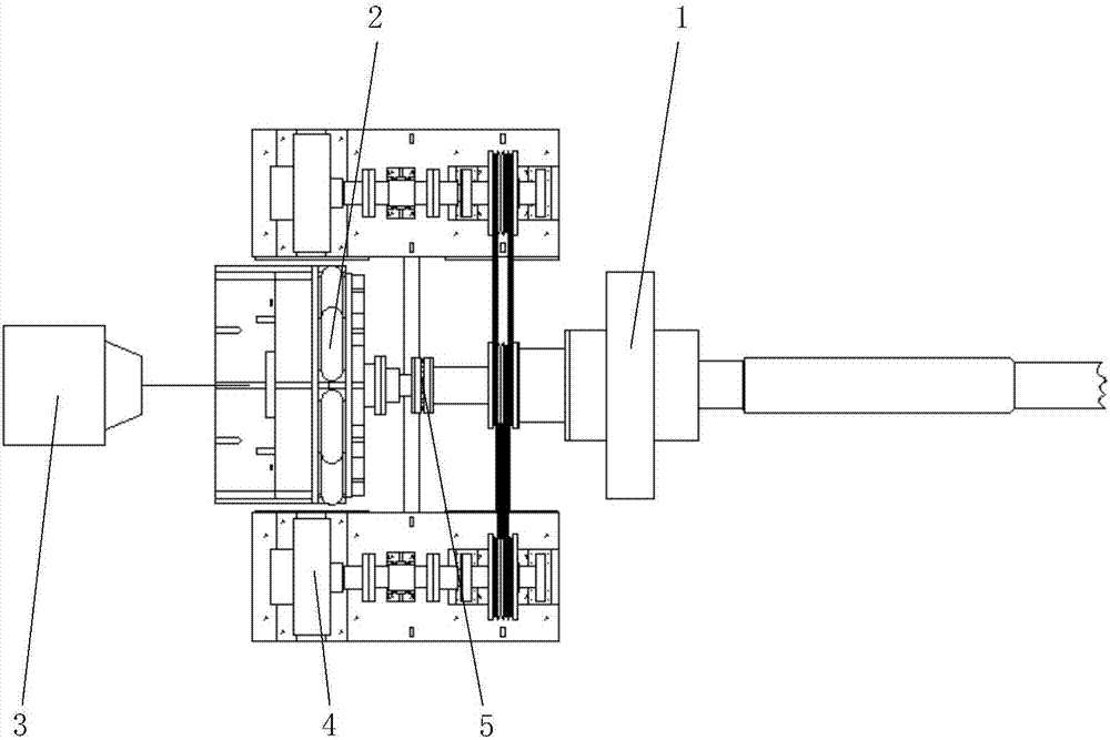
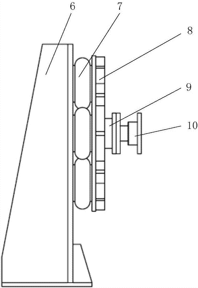
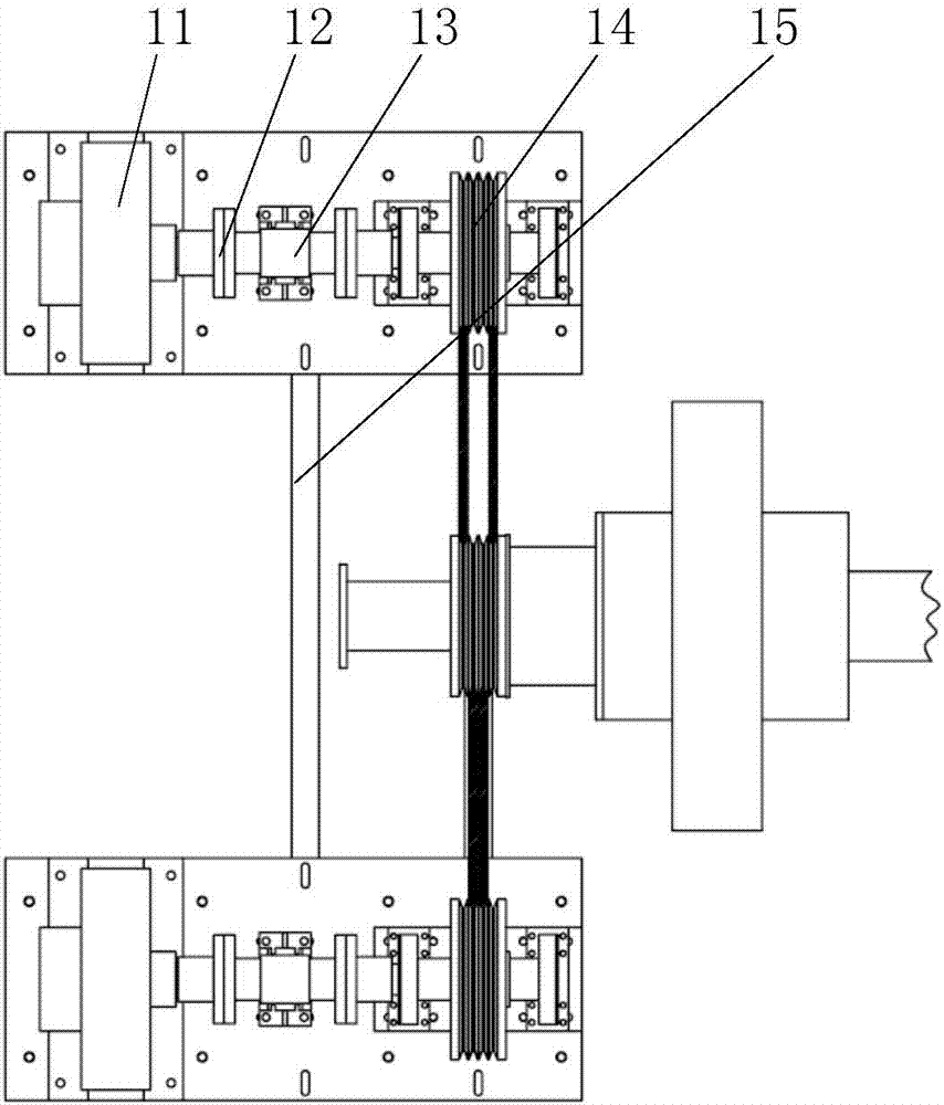
[0022] A loading test device for simulating a ship propeller of the present invention, the overall structure is as follows figure 1 As shown, the loading test device is mainly composed of a propeller simulation block 1, an axial static thrust loading device 2, a dynamic force loading device 3, a torque loading device 4 and a three-component dynamic force measuring device 5. Among them, the propeller simulation block 1 is installed at the end of the stern shaft of the propulsion shaft, and the axial thrust loading device 2 is connected with the propulsion shaft to realize the transmission of axial force; the dynamic force loading device 3 can realize dynamic force loading in the axial and radial directions; the torque The loading device 4 is realized by two magnetic powder brakes arranged symmetrically on both sides of the propulsion shaft; t...


PUM


Abstract

The invention relates to a loading test apparatus for simulating a ship thruster. The loading test apparatus comprises a propeller simulation block, an axial static thrust loading device, a dynamic force loading device, torque loading devices and a three-component dynamic force measuring device. The propeller simulation block is installed at the tail end of a propeller shaft screw shaft; the axial static thrust loading device is connected with the propeller shaft to realize axial force transmission; the dynamic force loading device can load dynamic forces along axial and radio directions; the torque loading devices are arranged at the two sides of the propeller shaft symmetrically and transmission between the torque loading devices and the propeller shaft is realized by a narrow V-band mechanism; and the three-component dynamic force measuring device can measure practical dynamic force component force values transmitted to X, Y, and X directions of the propeller shaft. With the test apparatus provided by the invention, various loads in mutual interaction between the propeller and the propeller shaft during the ship operating process can be simulated comprehensively; and loading of an axial static thrust, a dynamic force, and a torque can be realized.

Description

technical field [0001] The invention relates to a loading test device for simulating a ship propeller. Background technique [0002] The power from the main engine of the ship is transmitted to the propeller, which makes the propeller rotate, and at the same time, the thrust generated by the propeller rotation is transmitted to the hull through the thrust bearing to push the ship to sail. In this complex process, the propulsion motor transmits torque to the propeller, and at the same time, the propeller transmits static thrust through the propulsion axial thrust bearing, and because the propeller rotates in the uneven flow field at the stern, there is still unsteady thrust Component, thereby inducing the vibration of the propulsion shafting of the ship, causing the vibration of the hull and generating radiated noise. [0003] At present, relevant domestic universities and scientific research institutions have established some loading test devices for simulating ship propell...

Claims


Application Information

Patent Timeline
Patent Type & Authority Applications(China)
IPC IPC(8): G01M13/00
CPCG01M13/00
Inventor 邱跃统段勇王锁泉周凌波
Owner CHINA SHIP SCIENTIFIC RESEARCH CENTER (THE 702 INSTITUTE OF CHINA SHIPBUILDING INDUSTRY CORPORATION)
Learn More