Testing method for heat locating errors of linear shaft of vertical machining center

A vertical machining center and positioning error technology, applied to metal processing equipment, metal processing machinery parts, manufacturing tools, etc., can solve problems such as difficulty in installation and fixation, large number of capacitive sensors or eddy current sensors, and difficulty in guaranteeing, etc., to achieve Avoid the influence of thermal positioning error measurement, reduce auxiliary measurement man-hours, and improve accuracy

Inactive Publication Date: 2017-07-25
HEBEI UNIV OF TECH
View PDF3 Cites 11 Cited by
  • Summary
  • Abstract
  • Description
  • Claims
  • Application Information

AI Technical Summary

Problems solved by technology

This method solves the problem of measuring the thermal deformation of the grinding wheel spindle, but this method ignores the geometric positioning errors of each component of the machine tool (such as the installation gap error and pitch error of each part of the machine tool) and the clamping, alignment, and positioning of displacement sensors or standard parts. The influence of the deviation caused by the fixation on the measurement results, and the method needs to be based on the accurate determination of the relative position of the sensor and the grinding wheel spindle, which is difficult to guarantee in the actual measurement process, and the number of capacitive sensors or eddy current sensors used is large , It is also difficult to install and fix; the measurement efficiency is low, and it cannot meet the requirements of on-machine rapid detection in the process of CNC machining

Method used


Image

  • Testing method for heat locating errors of linear shaft of vertical machining center
  • Testing method for heat locating errors of linear shaft of vertical machining center
  • Testing method for heat locating errors of linear shaft of vertical machining center

Examples


Embodiment Construction

[0028] Specific examples of the present invention are given below. The specific embodiments are only used to further describe the present invention in detail, and do not limit the protection scope of the claims of the present application.

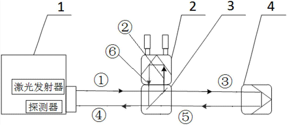
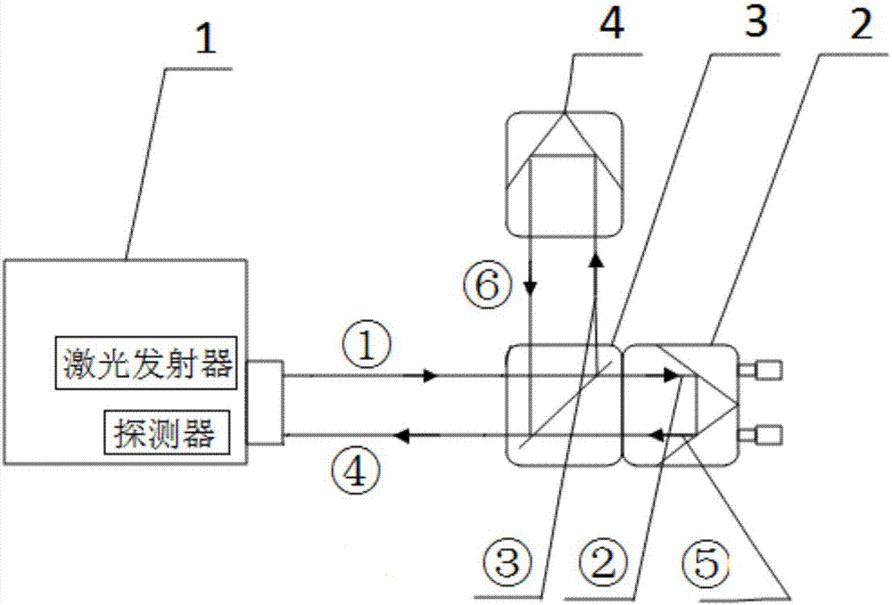
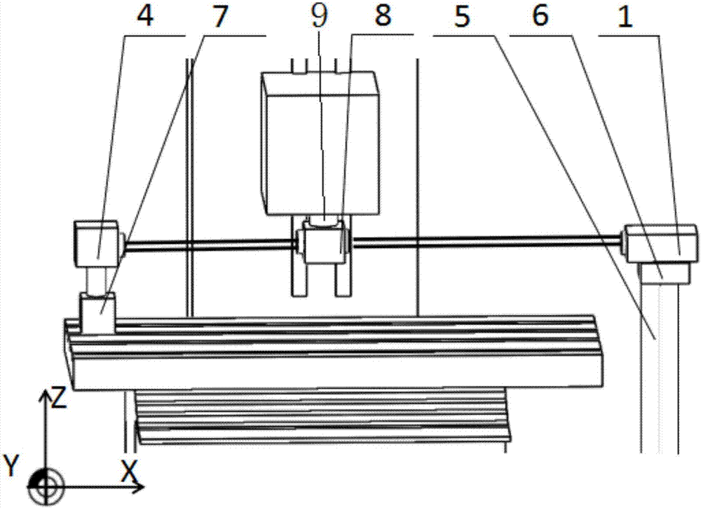
[0029] A thermal positioning error measuring device used in a test method for thermal positioning error of a linear axis of a vertical machining center of the present invention includes a laser interferometer, a bracket 5, a cloud platform 6, a first magnetic base 7, and a second magnetic base 9 And the computer that positioning error measurement software is installed; The laser interferometer includes a laser head 1, a linear interference mirror 8 and a second linear mirror 4; the linear interference mirror 8 includes a beam splitter 2 and a first linear mirror 3;

[0030] The principle of laser interferometer measuring positioning error is as follows: figure 1 As shown: the laser beam ① is generated by the laser head 1. When the laser be...


PUM


Abstract

The invention discloses a testing method for the thermal positioning error of a linear axis of a vertical machining center. This method first measures the positioning error of each measuring point of the linear axis of the vertical machining center at the initial moment, that is, the geometric error, and then measures the positioning error of each measuring point of the linear axis of the vertical machining center at any time, and the conditions remain unchanged during the two measurements , and finally make a difference between the two data to obtain the thermal positioning error of each measurement point of the linear axis of the vertical machining center at any time. In this way, the influence of the geometric errors of the various components of the machine tool on the thermal positioning error measurement is avoided, and the accuracy of the measurement results is improved. This method can quickly and efficiently complete the on-machine test requirements of the thermal positioning error of the linear axis, which not only avoids the influence of the geometric errors of the various components of the machine tool on the measurement of the thermal positioning error, but also avoids the use of displacement sensors or standard parts as well as clamping, finding The deviation problem caused by positive and fixed improves the accuracy of the measurement results.

Description

technical field [0001] The invention relates to the field of thermal positioning error measurement of numerical control machine tools, in particular to a testing method for the thermal positioning error of a linear axis of a vertical machining center. Background technique [0002] The thermal positioning error of the machine tool refers to the positioning error caused by the thermal deformation of the machine tool under the influence of thermal effects due to the uneven temperature field of the main parts of the machine tool due to high-speed cutting or rapid feed. With the development of CNC machine tools in the direction of high speed, high precision and large-scale compounding, the thermal positioning error of the motion axis of the machine tool plays a key role in improving the performance of the machine tool. Therefore, how to accurately, quickly and efficiently obtain the thermal positioning error of the motion axis to improve the machining accuracy of the machine tool...

Claims


Application Information

Patent Timeline
Patent Type & Authority Applications(China)
IPC IPC(8): B23Q17/00B23Q17/24
CPCB23Q17/00B23Q17/2452
Inventor 杨泽青韩靖杨伟东刘丽冰彭凯张俊峰李莉张艳蕊张玉佩李媛媛成玉飞陈英姝谭飏李增强张炳寅范敏
Owner HEBEI UNIV OF TECH
Why Eureka
Try Eureka