
Rotor staggered structure motor

A rotor and rotor core technology, applied in the magnetic circuit shape/pattern/structure, winding conductor shape/pattern/structure, electric components, etc., can solve the problem that the output torque fluctuation component of the motor winding is intensified and affects the degree of saturation of the motor material. , vibration and noise increase, to achieve the effect of reducing the amount of permanent magnets, iron core loss, wind friction loss and noise reduction

Active Publication Date: 2017-07-25
SOUTHEAST UNIV
View PDF3 Cites 1 Cited by
  • Summary
  • Abstract
  • Description
  • Claims
  • Application Information

AI Technical Summary

Problems solved by technology

For the unipolar magnetic field, there is a large constant component in the air gap magnetic field. When the constant component is large, it will affect the saturation degree of the motor material and increase the core loss; at the same time, the unipolar magnetic field also means that the high-order harmonic content Larger, the potential at both ends of the motor winding or the fluctuation component of the output torque will increase, and the vibration and noise will increase

Method used


Image

  • Rotor staggered structure motor
  • Rotor staggered structure motor
  • Rotor staggered structure motor

Examples


Embodiment 1

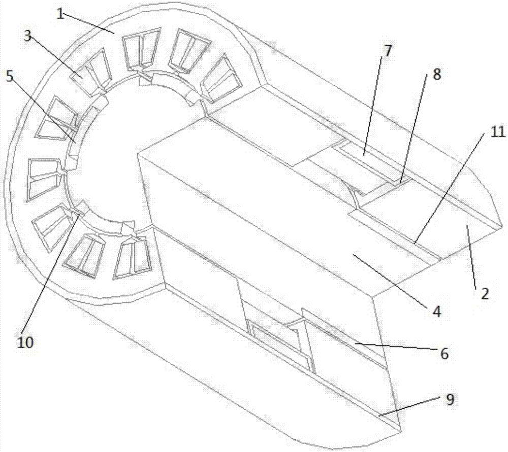
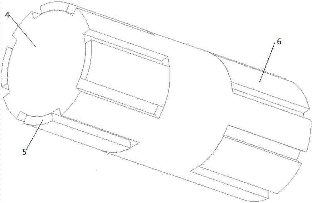
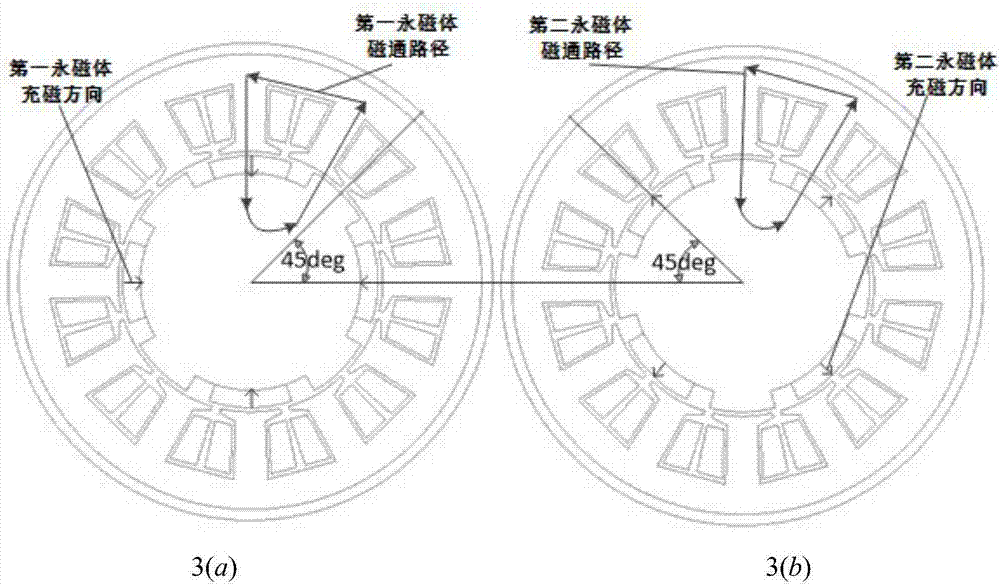
[0026] A motor with rotor dislocation structure, such as figure 1 As shown, it includes a stator and a rotor, wherein the stator includes a first stator core 1 , a second stator core 2 , an armature winding 3 , an excitation winding 7 and a casing 9 . The first stator core 1 and the second stator core 2 adopt a patch structure, and each stator core has 12 semi-closed slots evenly distributed along the circumference; the two stators are symmetrically distributed in the field winding 7 The two sides of the stator, and the slots of the two stators coincide completely along the axis. The armature windings 3 are symmetrically distributed in three phases and wound around the teeth of the first stator core 1 and the second stator core 2 . The field winding 7 is ring-shaped, arranged in the middle of the first stator core 1 and the second stator core 2 , and fixed on the field winding support 8 .

[0027] The rotor structure of the rotor dislocation structure motor is as follows f...

Embodiment 2

[0031] A motor with rotor dislocation structure, such as figure 1 As shown, it includes a stator and a rotor, wherein the stator includes a first stator core 1 , a second stator core 2 , an armature winding 3 , an excitation winding 7 and a casing 9 . The first stator core 1 and the second stator core 2 adopt a patch structure, and each stator core has 12 semi-closed slots evenly distributed along the circumference; the two stators are symmetrically distributed in the field winding 7 The two sides of the stator, and the slots of the two stators coincide completely along the axis. The armature windings 3 are symmetrically distributed in three phases and wound around the teeth of the first stator core 1 and the second stator core 2 . The field winding 7 is ring-shaped, arranged in the middle of the first stator core 1 and the second stator core 2 , and fixed on the field winding support 8 .

[0032] The rotor structure of the rotor dislocation structure motor is as follows f...


PUM


Abstract

The invention discloses a rotor staggered structure motor. The rotor staggered structure motor comprises a stator and a rotor, wherein the stator sleeves the outer side of the rotor; the stator comprises a first stator iron core, a second stator iron core, an armature winding, an exciting winding and a motor shell, the exciting winding is fixed on an annular exciting winding support, the first stator iron core and the second stator iron core are symmetrically arranged on two sides of the exciting winding, and teeth of the first stator iron core and teeth of the second stator iron core are not staggered in the peripheral direction; the rotor comprises a rotor iron core, a first permanent magnet and a second permanent magnet, a first groove corresponding to the first stator iron core and a second groove corresponding to the second stator iron core are staggered by Pi / n in the peripheral direction. According to the rotor staggered structure motor, through combined action of an iron core pole and a permanent magnet pole, the constant component and higher harmonic content of an air-gap field are reduced, so that the loss of iron cores is reduced, the fundamental current amplitude of the air-gap field is increased, and the utilization rate of the material is improved; and moreover, a rotor groove is filled with the permanent magnets, so that the wind drag and noise are reduced, the mechanical loss is reduced, and the operating efficiency of the motor is improved.

Description

technical field [0001] The invention relates to a motor with a rotor dislocation structure, which belongs to the motor technology. Background technique [0002] It is a common goal to use the motor space and material as much as possible, and at the same time we hope to save material and improve the performance of the motor. For example, for the slotted rotor motor, on the one hand, the slotting forms an uneven air gap, which generates an alternating magnetic field under the action of the excitation current; on the other hand, the rotor slotting brings space tooth harmonics, which increases the mechanical loss of the rotor and reduces the efficiency of the motor. . [0003] The air-gap magnetic fields in the motor include unipolar and bipolar fields. For the bipolar magnetic field, there is no DC component of the magnetic field, and even if there is a high-order harmonic component, its amplitude can be weakened by methods such as chute or short distance. For the unipolar m...

Claims


Application Information

Patent Timeline
Patent Type & Authority Applications(China)
IPC IPC(8): H02K1/27H02K3/28H02K1/14H02K3/48
CPCH02K1/14H02K1/2706H02K3/28H02K3/48
Inventor 付兴贺王建豪刘凯林明耀
Owner SOUTHEAST UNIV
Learn More