A kind of pasture grinder with three crushing chambers

A crushing chamber and crushing machine technology, applied in agricultural machinery and tools, agriculture, grain processing, etc., can solve the problems of being unable to crush, difficult to crush, and difficult to achieve knife alignment, etc., to achieve convenient and simple installation, avoid clogging the screen, and improve The effect of crushing efficiency

Active Publication Date: 2020-06-02
CHINA AGRI UNIV
View PDF9 Cites 0 Cited by
  • Summary
  • Abstract
  • Description
  • Claims
  • Application Information

AI Technical Summary

Problems solved by technology

The current pulverizers have low pulverization efficiency for hay pulverization, especially for forages with long fiber length and low brittleness, such as gramineous forages, which are difficult to pulverize
[0003] Grass grasses, such as Leymus chinensis, have long fibers and low stiffness of stem nodes, so it is difficult for the shredder to achieve knife alignment
The shredded pasture is directly thrown out, the size is large and uneven, and the crushing effect is poor. If the hammer mill is directly used for crushing, the long fibers will quickly contact the screen, and the long fibers that cannot pass the screen will hang on the screen holes, which will cause The sieve is clogged and cannot be crushed
Because the screen plane of the vertical grinder is perpendicular to the main shaft, when the fiber hangs on the screen hole, it cannot return to the crushing chamber, and there is also the problem of screen blockage

Method used


Image

  • A kind of pasture grinder with three crushing chambers
  • A kind of pasture grinder with three crushing chambers
  • A kind of pasture grinder with three crushing chambers

Examples


Embodiment Construction

[0029] The present invention will be further described below in conjunction with the accompanying drawings and specific embodiments. It should be emphasized that the following description is only exemplary and not intended to limit the scope of the invention and its application.

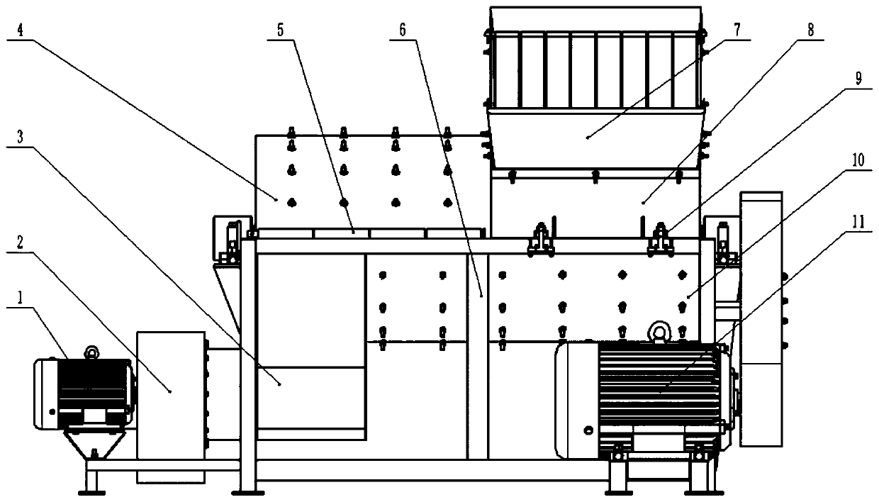
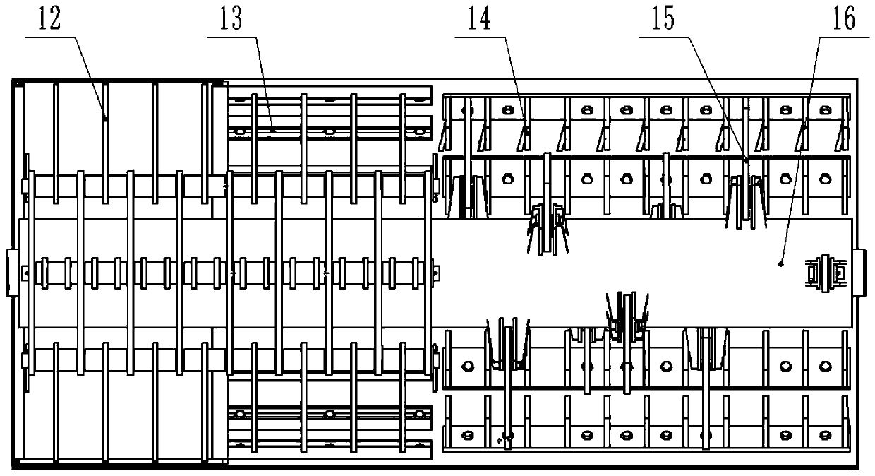
[0030] Such as Figure 1-Figure 2 Shown is a three-chamber forage grinder provided by the present invention, which includes a frame 6, a housing, a main shaft 16, a fixed knife 15, a moving knife 16, a concave tooth plate 13 and a fan 2.

[0031] The upper left cover 4 and the upper right cover 8 are connected to form an upper casing, and the upper left cover 4 and the upper right cover 8 are sealed by rubber; the upper casing and the lower casing 10 form a casing. The lower casing 10 is fixed on the frame 6 by welding. The upper left cover 4 and the upper right cover 8 are respectively connected to the lower housing 10 through hinges 5 and fixed through a bolt locking mechanism 9 . Loosen the bol...


PUM


Abstract

The invention relates to a pasture pulverizer with three pulverizing chambers. The pasture pulverizer sequentially comprises a pre-pulverizing chamber, a tooth plate pulverizing chamber and a screen pulverizing discharging chamber. Fixed cutters are distributed on the inner wall of a lower shell body of the pre-pulverizing chamber. A feeding port is formed in an upper shell body of the pre-pulverizing chamber to be connected with a feeding hopper. Tooth plates are distributed on the inner walls of an upper shell body and a lower shell body of the tooth plate pulverizing chamber. Tooth plates are distributed on the inner wall of an upper shell body of the screen pulverizing discharging chamber, and a discharging port is formed in a lower shell body of the discharging chamber to be connected with a discharging hopper. The discharging port is provided with a screen, and the discharging hopper is connected with a draught fan. A main shaft is located in a shell and arranged in the longitudinal direction of the shell, movable cutters are distributed on the part, located in the pre-pulverizing chamber, of the main shaft, and hammer sheets are distributed on the part, located in the tooth plate pulverizing chamber and the screen pulverizing discharging chamber, of the main shaft. A three-pulverizing-chamber structure is adopted in the pasture pulverizer, after being gradually pulverized in the different pulverizing chambers, the pasture reaches the screen to be sieved, and efficient pulverizing of the pasture low in brittleness and long in fiber can be achieved.

Description

technical field [0001] The invention belongs to the technical field of animal husbandry machinery, in particular to a grass grinder with three grinding chambers. Background technique [0002] The development of animal husbandry and the country's requirements for the recycling of farmland waste have promoted the development and application of forage processing equipment. Crushing grass can reduce the size of the grass, reduce the bulk density, increase the specific surface area, and speed up the contact reaction speed. The shredded forage can be used directly for feeding, or it can be prepared for subsequent processing. The current pulverizers have low pulverization efficiency for hay pulverization, especially for pastures with long fiber length and low brittleness, such as gramineous pastures, which are difficult to pulverize. [0003] Grass grasses, such as Leymus chinensis, have long fibers and low stiffness of stem nodes, so it is difficult for the shredder to achieve k...

Claims


Application Information

Patent Timeline
Patent Type & Authority Patents(China)
IPC IPC(8): B02C13/04B02C13/13B02C13/20B02C13/26B02C23/20B02C23/02A01F29/00A01F29/12A01F29/09
CPCA01F29/00A01F29/09A01F29/12B02C13/04B02C13/13B02C13/20B02C13/26B02C23/02B02C23/20
Inventor 王光辉陈启新王志琴王德成
Owner CHINA AGRI UNIV
Why Eureka
Try Eureka