Dismounting and mounting device for moving cone liner plate of HP type cone crusher
A technology of cone crushing and moving cone liner, which is applied in the direction of grain processing, etc., can solve the problems of broken moving cone, easily damaged locking bolts, and failure of enterprises to meet the requirements, so as to prolong the service life, reduce the damage of accessories, and disassemble high efficiency effect
- Summary
- Abstract
- Description
- Claims
- Application Information
AI Technical Summary
Problems solved by technology
Method used
Image

Examples
Embodiment 1
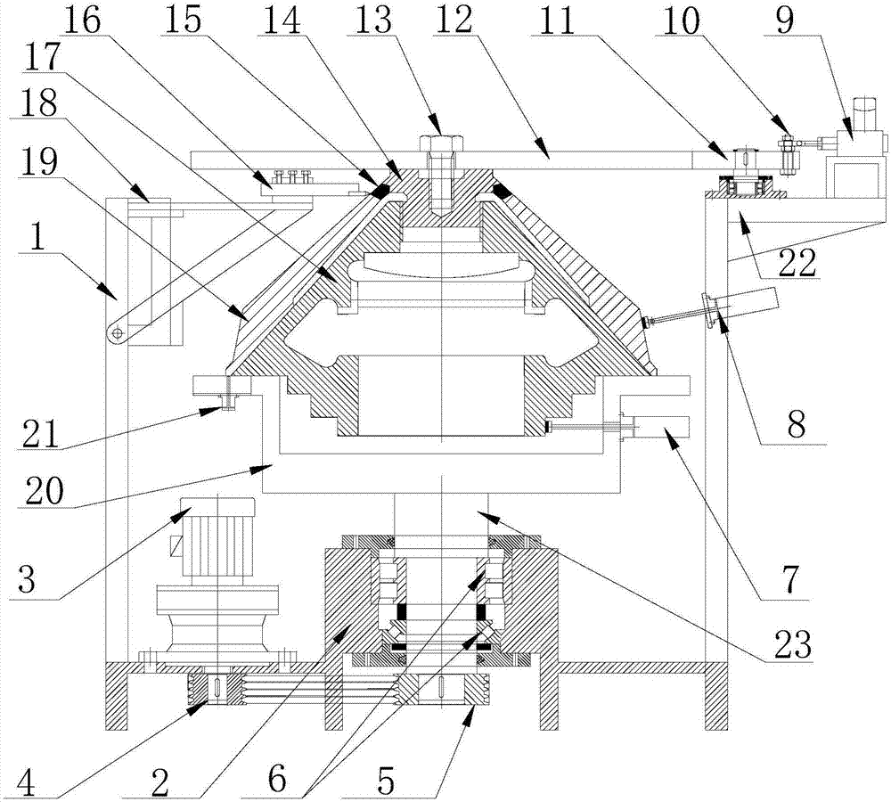
[0026] Such as Figure 1 to Figure 6As shown, the HP-type cone crusher motor cone liner dismounting device of the present invention includes a moving cone assembly and a frame 1. The moving cone assembly includes a moving cone 17 and a moving cone that is matched on the outer surface of the moving cone 17. The cone liner 19 is connected to the top of the moving cone 17 with a locking bolt 14 for locking the moving cone liner 19, and the locking bolt 14 is matched with the moving cone liner 19 with a corresponding cutting ring 15; The bottom of the frame 1 is provided with a rotating base 2 and a reduction motor 3, the rotating shaft of the reduction motor runs through the bottom of the frame 1, and a driving pulley 4 is installed, and the rotation base 2 is matched with a bearing group 6 Main shaft 23; the lower end of the main shaft 23 runs through the bottom of the frame 1, and is provided with a driven pulley 5 that is in transmission with the driving pulley 4, and the uppe...
Embodiment 2
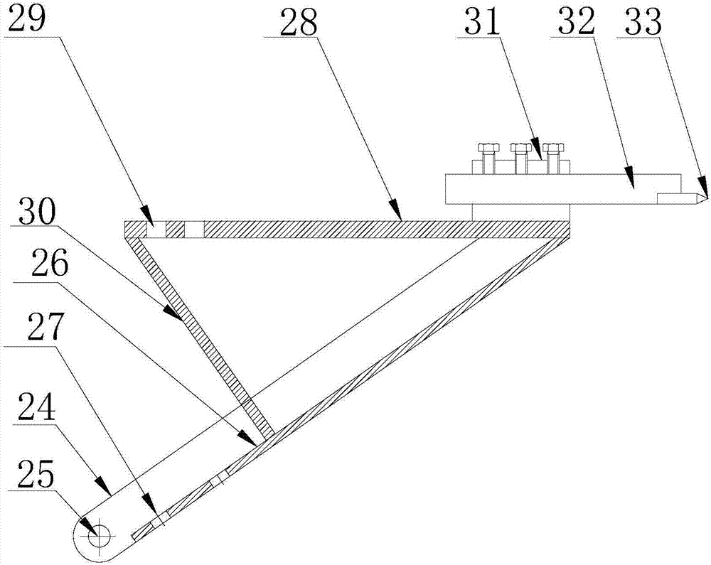
[0028] As a preference, in order to better realize the present invention, it is further optimized on the basis of the above-mentioned embodiments, and the following arrangement structure is adopted in particular: the cutting assembly fixing bracket 18 includes a cutting assembly arranged on the inner side of the upper part of the frame 1 The lower fixed plate 53 and the upper fixed plate 54 of the cutting assembly; also include a bracket 24, the lower end of which is provided with a rotating pin hole 25, and the rotating pin hole 25 is fixed to the cutting assembly arranged on the frame 1 The support fixing pin hole 52 is matched by a pin shaft; the upper end of the support 24 is connected with a horizontally arranged cutter head flat seat 28, and a flat plate seat fixing bolt hole 29 is arranged on the cutter head flat seat 28. The cutting assembly The upper fixing plate 54 is provided with a bolt hole adapted to the flat seat fixing bolt hole 29, and is matched with a corresp...
Embodiment 3
[0030] As preferably, in order to realize the present invention better, optimize further on the basis of above-mentioned embodiment, especially adopt following arrangement structure: between described cutter head plate base 28 and bottom plate 26, be connected with stable reinforcing plate 30, improve The mechanical stability is improved, the accuracy of the cutting tool assembly 16 is improved when cutting, the damage to the moving cone assembly is reduced, and the disassembly is facilitated.
PUM
 Abstract
Description
Claims
Application Information
 - Generate Ideas
- Intellectual Property
- Life Sciences
- Materials
- Tech Scout
- Unparalleled Data Quality
- Higher Quality Content
- 60% Fewer Hallucinations
Browse by: Latest US Patents, China's latest patents, Technical Efficacy Thesaurus, Application Domain, Technology Topic, Popular Technical Reports.
© 2025 PatSnap. All rights reserved.Legal|Privacy policy|Modern Slavery Act Transparency Statement|Sitemap|About US| Contact US: help@patsnap.com