Hydraulic overturning steel ladle slag-pouring vehicle
A technology for dumping slag trucks and ladles, which is applied to casting molten material containers, metal processing equipment, casting equipment, etc., and can solve problems such as occupied driving time, reduced production efficiency, and longer operating cycle, so as to reduce operating cycle and improve The effect of production efficiency and load balancing
- Summary
- Abstract
- Description
- Claims
- Application Information
AI Technical Summary
Problems solved by technology
Method used
Image

Examples
Embodiment 1
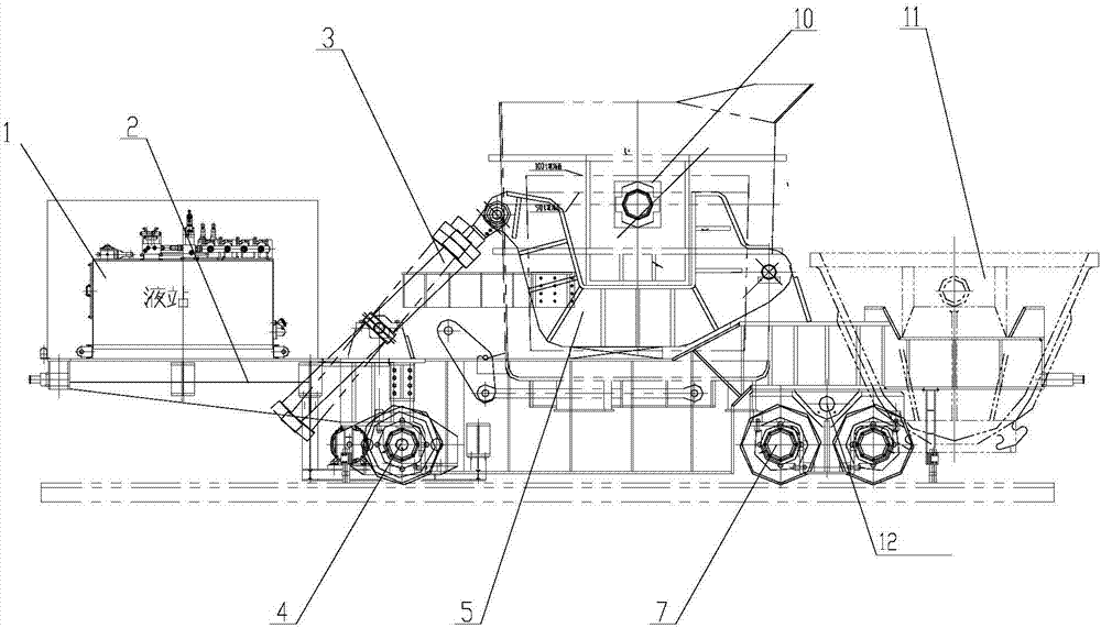
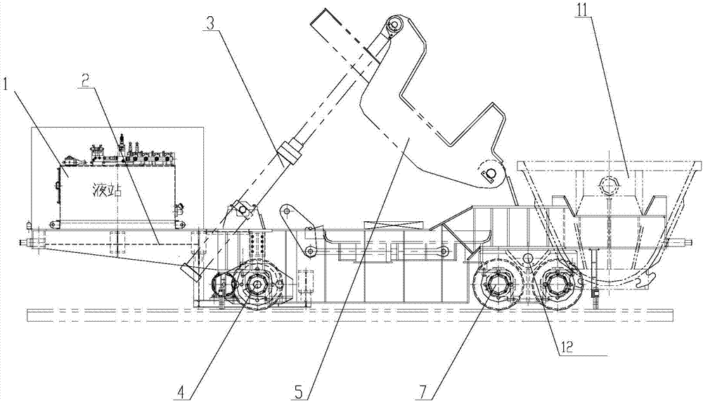
[0026] like Figure 1-4 As shown, a hydraulic tipping ladle dumping vehicle of the present invention includes: a vehicle frame 2 and a driving device, and the front and rear sides of the lower end of the vehicle frame 2 are respectively provided with a drive wheel 4 and a balance vehicle frame 2 for controlling the forward / backward movement of the vehicle The upper end of the vehicle frame 2 is provided with a hydraulic tipping device for placing a ladle 10, and the rear of the vehicle frame 2 is provided with a slag pan 11 for holding steel slag; the driving device acts on the driving wheel 4 .
[0027] The hydraulic tipping ladle dumping equipment is set to be movable. After the steel ladle 10 is refined, the steel ladle 10 is directly hoisted into the hydraulic tipping ladle dumping truck of the present invention. The ladle 10 hydraulic tipping and slag dumping process is completed on the vehicle, no additional work time is added, and the production efficiency is greatly i...
Embodiment 2
[0031] Embodiment 2. On the basis of the above embodiments, the hydraulic tilting device includes a hydraulic cylinder 3, a crank arm assembly and a hydraulic station 1 that provides power for the hydraulic cylinder 3;
[0032] The hydraulic station 1 is installed on the front of the vehicle frame 2, and the hydraulic cylinder 3 is arranged adjacent to the hydraulic station 1. The crank arm assembly is used for fixing and tipping the ladle 10, and one end thereof is connected to the telescopic end of the hydraulic cylinder 3. Connected, the other end is hinged with the vehicle frame 2, so that under the action of the hydraulic cylinder 3, the steel ladle 10 can be rotated clockwise / counterclockwise at a certain angle, so that the steel slag in the steel ladle 10 is poured into the slag pan 11.
[0033] The hydraulic station 1 provides the tipping power for the hydraulic cylinder 3, and the crank arm rotation is realized through the extension and shortening of the hydraulic cyli...
Embodiment 3
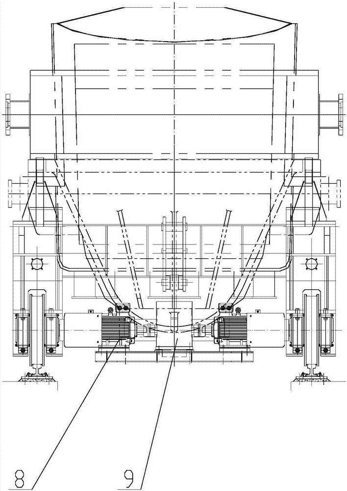
[0035] Embodiment 3. On the basis of the above embodiments, the crank arm assembly includes two tilting arms 5 and synchronous beams 6 that cooperate with each other to fix the ladle, and the two ends of the synchronous beam 6 are connected to the two tilting arms respectively. One end of the arm 5 and the other end of the tilting arm 5 are hinged to the vehicle frame 2; the synchronous beam 6 is a V-shaped structure, and the top two ends of the V-shaped structure are connected to the tilting arm 5 respectively.
[0036] The synchronous beam 6 is V-shaped and bypasses the ladle to better ensure the stability and synchronization of the two tilting arms 5. During the tipping process, a certain degree of synchronization can be ensured, and the stiffness of the tilting arms 5 can be improved. Safe and reliable.
PUM
 Abstract
Description
Claims
Application Information
 - R&D Engineer
- R&D Manager
- IP Professional
- Industry Leading Data Capabilities
- Powerful AI technology
- Patent DNA Extraction
Browse by: Latest US Patents, China's latest patents, Technical Efficacy Thesaurus, Application Domain, Technology Topic.
© 2024 PatSnap. All rights reserved.Legal|Privacy policy|Modern Slavery Act Transparency Statement|Sitemap