Supercharge Your Innovation With Domain-Expert AI Agents!

Chemical and mechanical polishing equipment

A chemical machinery and equipment technology, applied in the field of chemical mechanical polishing equipment, can solve problems such as substandard quality of polishing liquid, achieve good polishing effect, eliminate eddy current phenomenon, and reduce production costs.

Inactive Publication Date: 2017-07-28
HUANGHE S & T COLLEGE
View PDF7 Cites 0 Cited by
  • Summary
  • Abstract
  • Description
  • Claims
  • Application Information

AI Technical Summary

Problems solved by technology

[0006] In view of the above situation, in order to overcome the defects of the prior art, the object of the present invention is to provide a kind of chemical mechanical polishing equipment, by improving the batching mechanism of the polishing liquid, the quality of the polishing liquid is improved, the polishing effect is improved, and the polishing effect in the prior art is solved. The problem of substandard liquid quality

Method used


Image

  • Chemical and mechanical polishing equipment
  • Chemical and mechanical polishing equipment
  • Chemical and mechanical polishing equipment

Examples


Embodiment 1

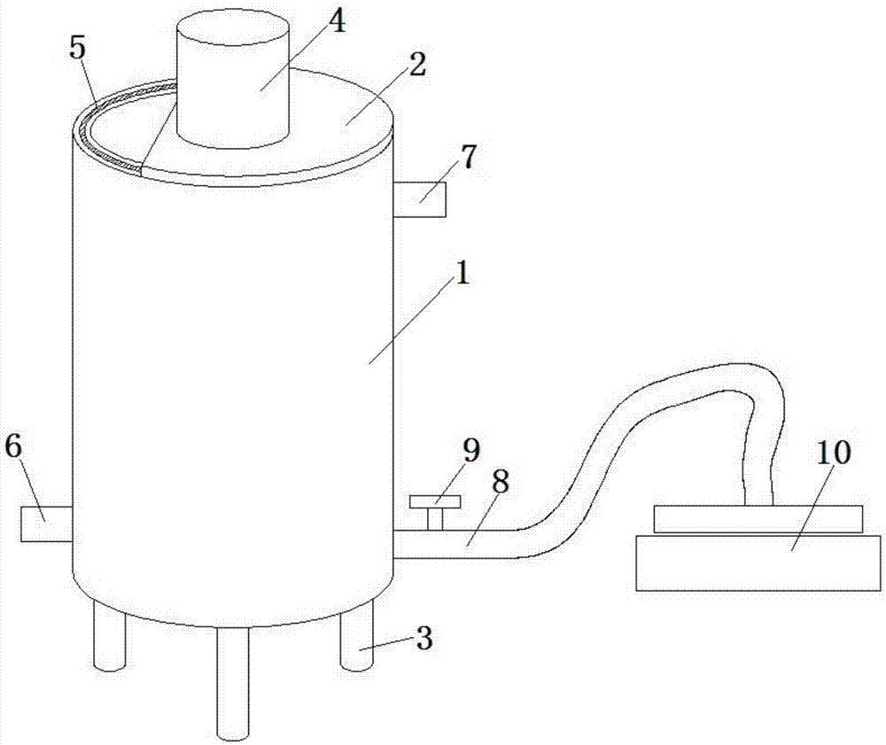
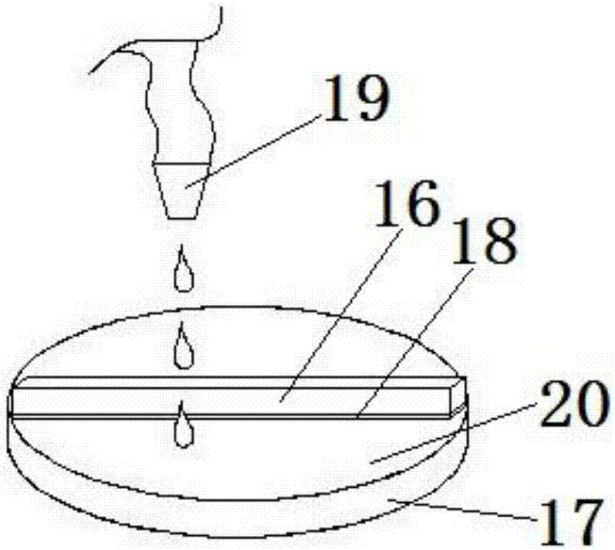
[0031] refer to Figure 1-4 , a kind of chemical mechanical polishing equipment, comprises the batching bucket 1 that is used for preparing polishing liquid and the polisher 10 that is used for polishing wafer 20, and described polisher 10 is connected with batching bucket 1 through conveying pipe 8, and batching bucket 1 completes After preparing the polishing liquid, the polishing liquid is transported to the polisher 10 through the delivery pipe 8, and then the wafer 20 is polished.

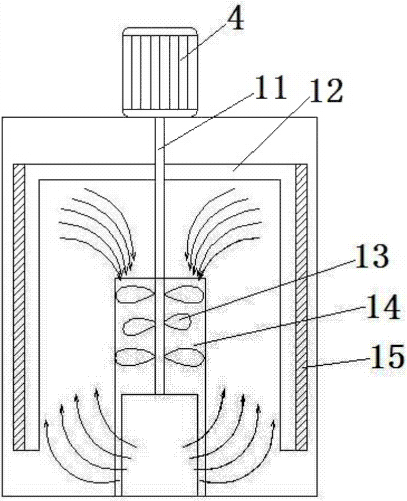
[0032] The bottom of the batching barrel 1 is provided with a bracket 3, and the top is provided with a bung 2. The bung 2 is provided with a feeding opening, and the lower end of the bucket 1 is provided with a discharge opening, and a valve 9 is provided at the discharge opening. Described batching barrel 1 is provided with stirring device, and stirring device comprises stirring shaft 11 and the stirring blade 13 that is fixed on the stirring shaft 11, and described stirring blade 13 quantit...

Embodiment 2

[0037] A stirring paddle 12 is also fixed on the stirring shaft 11 , the stirring paddle 12 is an inverted U shape, and the stirring paddle 12 can stir the materials outside the central cylinder 14 . The side of described stirring paddle 12 is fixed with the bucket wall scraper 15 that vertically arranges, and the distance between the side of bucket wall scraper 15 and the inner wall of batching bucket 1 is 0.2cm, when stirring work, bucket wall scraper 15 rotates with stirring shaft 11 , to scrape off the material adhered to the inner wall of the batching barrel 1, so as to achieve the purpose of cleaning the barrel wall.

Embodiment 3

[0039]The motor 4 is vertically fixed on the surface of the center of the bung 2 by four screws, so that it can be easily disassembled.


PUM


Abstract

The invention relates to the field of wafer machining, in particular to chemical and mechanical polishing equipment. Aiming at the problem of unqualified polishing liquid in the prior art, the following scheme is provided; the chemical and mechanical polishing equipment comprises a batching barrel for preparing polishing liquid, and a polishing machine for polishing a wafer; the polishing machine is connected with the batching barrel through a conveying pipe; and after the batching barrel finishes preparation of the polishing liquid, the polishing liquid is conveyed to the polishing machine by the conveying pipe for polishing the wafer. A discharge port is formed in the lower end of the batching barrel, and is provided with a valve; the discharge port is connected with the polishing machine through the conveying pipe; the polishing machine includes a polishing disc, a polishing liquid conveying port fixed above the polishing disc, a polishing head positioned above the polishing disc, and a polishing pad mounted on the lower surface of the polishing head and with a curve profile; the wafer to be polished is placed on the polishing disc, and rotates along with the polishing disc; and polishing liquid output port directly conveys the polishing liquid to the wafer.

Description

technical field [0001] The invention relates to the field of wafer processing, in particular to chemical mechanical polishing equipment. Background technique [0002] In the production process of large-scale integrated circuits, planarizing the deposition on the wafer is a necessary and frequent process. At present, the chemical mechanical polishing (CMP) process is mainly used to complete this process. The chemical mechanical polishing machine is the main equipment to complete this process. In the current polishing process, when the polishing liquid needs to be replaced, the polishing equipment must be shut down, and then the used polishing liquid is discharged, and the ingredients are mixed according to the proportion of each component in the polishing liquid, and poured into the barrel of the polishing equipment. After stirring for a certain period of time, this batching method is time-consuming and laborious, and the work efficiency is low; and the polishing liquid is ...

Claims


Application Information

Patent Timeline
Patent Type & Authority Applications(China)
IPC IPC(8): B24B37/34B24B57/02
CPCB24B37/34B24B57/02
Inventor 穆国华付志豪王士瑞徐萍肖娜
Owner HUANGHE S & T COLLEGE
Features
  • R&D
  • Intellectual Property
  • Life Sciences
  • Materials
  • Tech Scout
  • Unparalleled Data Quality
  • Higher Quality Content
  • 60% Fewer Hallucinations
Learn More