Quantitative conveying mechanism and catalysis degreasing furnace

A technology of conveying mechanism and feeding trough, which is applied to conveyors, mixers, transportation and packaging, etc. It can solve problems such as safety accidents, high production and maintenance costs, and surface oxidation of workpieces, so as to avoid safety accidents and reduce production and maintenance costs. Effect

Pending Publication Date: 2017-07-28
SHENZHEN SINTERZONE TECH CO LTD
View PDF11 Cites 3 Cited by
  • Summary
  • Abstract
  • Description
  • Claims
  • Application Information

AI Technical Summary

Problems solved by technology

The removal of the adhesive in the traditional process requires the use of nitric acid as a catalyst. However, nitric acid has some disadvantages as a catalyst. For example, nitric acid is highly corrosive, and it is easy to damage the human body during use. There are potential safety hazards. It is easy to cause surface oxidation of the workpiece; in addition, nitric acid will also produce a large amount of nitrogen oxides during the catalytic process, thereby causing environmental pollution
Based on the above problems, people have developed a process using oxalic acid as a catalyst. However, oxalic acid is solid at room temperature, and traditional liquid material feeding mechanisms such as plunger pumps are difficult to apply, while most of the traditional solid feeding mechanisms use compression. It is difficult to realize the quantitative delivery of oxalic acid in this scheme, and the inflow of air during the catalytic degreasing process will cause serious safety accidents; in addition, there are complex control systems and automatic mechanisms in the prior art to achieve quantitative delivery. The solid feeding mechanism for conveying, however, this kind of scheme has a complex structure, high production and maintenance costs, and is not conducive to improving the market competitiveness of products

Method used

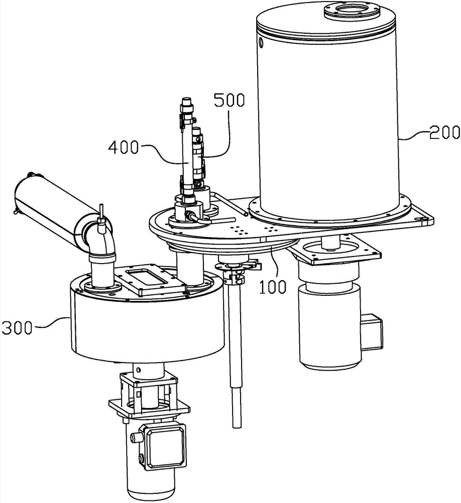
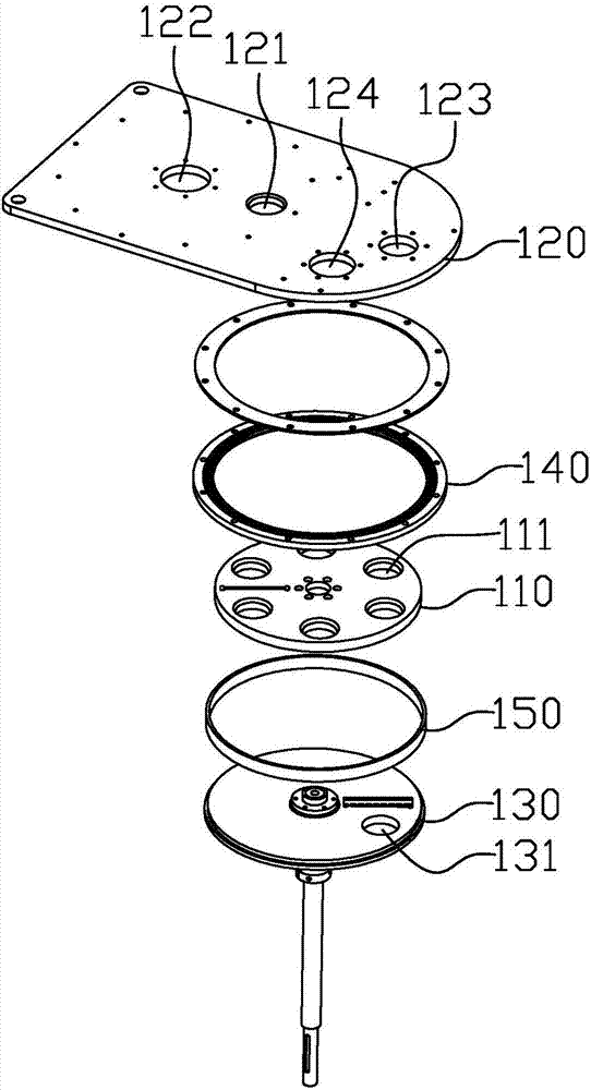
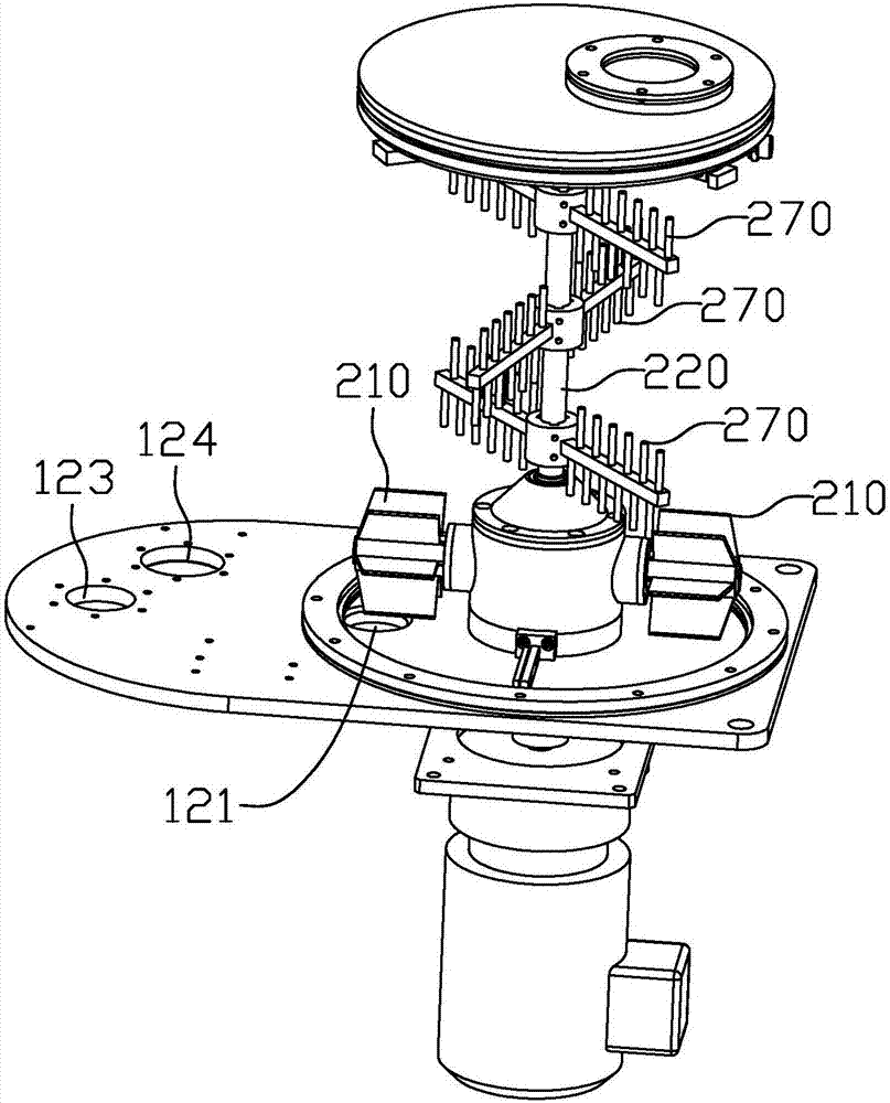

Image

  • Quantitative conveying mechanism and catalysis degreasing furnace
  • Quantitative conveying mechanism and catalysis degreasing furnace
  • Quantitative conveying mechanism and catalysis degreasing furnace

Examples


Embodiment Construction

[0025] The idea, specific structure and technical effects of the present invention will be clearly and completely described below in conjunction with the embodiments and accompanying drawings, so as to fully understand the purpose, scheme and effect of the present invention. It should be noted that, in the case of no conflict, the embodiments in the present application and the features in the embodiments can be combined with each other.

[0026] It should be noted that, unless otherwise specified, when a feature is called "fixed" or "connected" to another feature, it can be directly fixed and connected to another feature, or indirectly fixed and connected to another feature. on a feature. In addition, descriptions such as up, down, left, and right used in the present invention are only relative to the mutual positional relationship of the components of the present invention in the drawings.

[0027] Also, unless defined otherwise, all technical and scientific terms used herei...


PUM


Abstract

The invention relates to the field of automatic devices, and discloses a quantitative conveying mechanism and a catalysis degreasing furnace. The quantitative conveying mechanism comprises a feed plate, a top plate and a bottom plate, wherein the top plate and the bottom plate are arranged on the upper side and the lower side of the feed plate correspondingly. Feed grooves are formed in the feed plate. A feed port is formed in the top plate. A discharge port is formed in the bottom plate. The feed plate can move relative to the top plate and the bottom plate. When each feed groove passes by the feed port, materials enter the feed groove from the feed port and make the feed groove full filled with the materials, and when each feed groove passes by the discharge port, the materials in the feed groove are discharged through the discharge port. According to the quantitative conveying mechanism and the catalysis degreasing furnace, by means of reciprocating of the feed plate, provided with the fixed-volume feed grooves, between the feed port and the discharge port, quantitative conveying of the materials can be achieved, no complex control systems or automatic mechanisms need to be used, and therefore the production and maintenance cost of the device is greatly reduced; and meanwhile, conveying of oxalic acid is achieved through the mechanical structure, compressed air does not need to be used as power, and therefore safety accidents can be effectively avoided.

Description

technical field [0001] The invention relates to the field of automation equipment, in particular to a conveying mechanism and a catalytic degreasing furnace using the conveying mechanism. Background technique [0002] The process of metal / ceramic powder injection molding includes the step of using metal powder and binder to form a green body. The green body needs to remove the binder (catalytic degreasing) before sintering to obtain a complete metal phase. The removal of the adhesive in the traditional process requires the use of nitric acid as a catalyst. However, nitric acid has some disadvantages as a catalyst. For example, nitric acid is highly corrosive, and it is easy to damage the human body during use. There are potential safety hazards. It is easy to cause surface oxidation of the workpiece; in addition, nitric acid will also produce a large amount of nitrogen oxides during the catalytic process, thereby causing environmental pollution. Based on the above problems,...

Claims


Application Information

Patent Timeline
Patent Type & Authority Applications(China)
IPC IPC(8): B65G65/48B65G69/00B65G69/20B01F7/00B01F7/30B01F15/00B01D7/00B22F3/10B22F3/22
CPCB01D7/00B65G65/4818B65G69/00B65G69/20B22F3/003B22F3/1025B22F3/225B65G2201/04B01F27/074B01F27/112B01F27/951B01F35/30B01F2101/45
Inventor 骆接文林利宏
Owner SHENZHEN SINTERZONE TECH CO LTD
Why Eureka
Try Eureka