Cotton collection bucket of disc type plucker

The technology of a disc grabbing machine and a cotton hopper is applied in the field of cotton collection hoppers, which can solve the problems of clogging the cotton hopper with cotton lumps, deal with mechanical damage, trouble in recycling iron scraps, etc., so as to reduce the probability of clogging, simplify the operation and operation handy effect

Inactive Publication Date: 2017-07-28
湖州南浔凯普纺织有限公司
View PDF6 Cites 2 Cited by
  • Summary
  • Abstract
  • Description
  • Claims
  • Application Information

AI Technical Summary

Problems solved by technology

Since the cotton raw material contains impurities such as iron filings, if it is not treated in time, it will cause damage to the subsequent processing machinery. At present, it is usually used to set ring-shaped grooves and convex strips on the inner wall of the cotton collection bucket, and place magnets in the grooves or convex strips. Strips are used to absorb iron filings. This method requires manual scraping and recycling of iron filings layer by layer. It is not only troublesome to operate but also difficult to completely scrape iron filings, which will affect subsequent use.
In addition, the existing cotton collection hopper often has the problem that cotton bundles and cotton blocks block the cotton collection hopper
Therefore, the existing cotton collection hopper has the problems of troublesome iron filings recovery and easy clogging

Method used


Image

  • Cotton collection bucket of disc type plucker
  • Cotton collection bucket of disc type plucker
  • Cotton collection bucket of disc type plucker

Examples


Embodiment Construction

[0015] The present invention will be further described below in conjunction with the accompanying drawings and embodiments, but not as a basis for limiting the present invention.

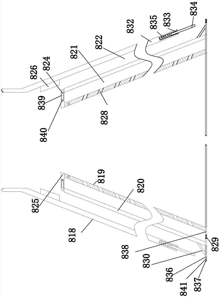
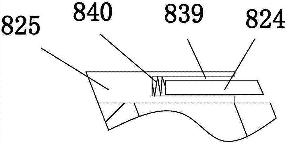
[0016] Example. A cotton collecting hopper of a disc plucking machine is constituted as Figure 1 to Figure 5 As shown, it includes an outer shell 818 and an inner shell 819 with a tapered cross-section, and the height of the inner shell 819 is lower than that of the outer shell 818. A partition 820 is provided between the outer shell 818 and the inner shell 819, and the inside of the partition 820 is a guide. The wind layer 821, the outer side of the partition 820 is a debris storage layer 822; the upper end of the debris storage layer 822 is provided with a fixed cover plate 823 and a movable iron plate 824, and the upper end of the wind guide layer 821 is provided with a top baffle 825, and the top baffle A movable groove 839 corresponding to the position of the movable iron plate 824 is provide...


PUM


Abstract

The invention discloses a cotton collection bucket of a disc type plucker. The cotton collection bucket includes an outer shell (818) and an inner shell (819); a baffle plate (820) is arranged between the outer shell (818) and the inner shell (819), the inner side of the baffle plate (820) is an air guide layer (821), and the outer side of the baffle plate (820) is a debris storage layer (822); a fixed cover plate (823) and a movable iron plate (824) are arranged at the upper end of the debris storage layer (822), a top baffle plate (825) is arranged at the upper end of the air guide layer (821), a movable groove (839) corresponding to the position of the movable iron plate (824) is formed in the top baffle plate (825), and a movable spring (840) is arranged between the movable groove (839) and the movable iron plate (824); an electromagnet(826) is arranged above the movable iron plate (824) and is connected with a controller (827), a through hole (828) is formed in the inner shell (819), and an air inlet (829) is formed in the bottom of the air guide layer (821). The cotton collection bucket of the disc type plucker has the advantages of making scrap iron recycling convenient and reducing the occurrence frequency of blocking.

Description

technical field [0001] The invention relates to a disc catching machine, in particular to a cotton collection hopper of the disc catching machine. Background technique [0002] Cotton yarn used in the textile industry is made from cotton fibers processed through the spinning process. In this process, it is first necessary to use the plucking machine to grab cotton bundles and cotton blocks from the bundled cotton raw materials, and then transport them to the following machinery through negative pressure pipelines for processing and production in the next step. Since the cotton raw material contains impurities such as iron filings, if it is not treated in time, it will cause damage to the subsequent processing machinery. At present, it is usually used to set ring-shaped grooves and convex strips on the inner wall of the cotton collection bucket, and place magnets in the grooves or convex strips. This method requires manual scraping and recycling of iron filings layer by laye...

Claims


Application Information

Patent Timeline
Patent Type & Authority Applications(China)
IPC IPC(8): D01G7/06D01G31/00
CPCD01G7/06D01G31/003D01G31/006
Inventor 沈新荣周云芬
Owner 湖州南浔凯普纺织有限公司
Why Eureka
Try Eureka