

Waterstop pouring device
A technology of waterstop and water tank, which is applied in construction, building structure, and on-site preparation of building components, can solve problems such as hidden dangers of water seepage, and achieve the effect of improving pouring efficiency
- Summary
- Abstract
- Description
- Claims
- Application Information
AI Technical Summary
Problems solved by technology
Method used
Image

Examples
Embodiment 1
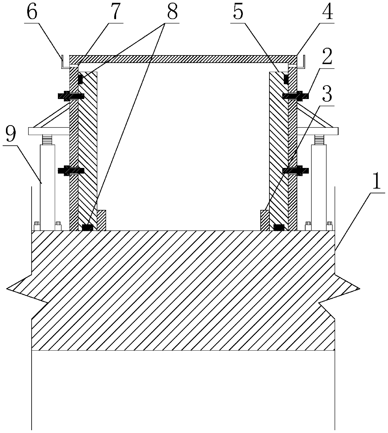
[0024] Such as figure 1 and figure 2 As shown, the waterstop pouring device includes a base plate 1 and a plurality of side formworks 5, the side formworks 5 are all installed on the base plate 1, and the plurality of side formworks 5 enclose the pouring space of the building body, and also include U-shaped card Groove 4, the U-shaped groove 4 is in the shape of a groove, the U-shaped groove 4 is buckled on the bottom plate 1, and the bottom or side of the U-shaped groove 4 is also provided with a hole for pouring material, and a part of the side formwork 5 is attached to the inner wall surface of one side of the U-shaped card slot 4, and another part of the side template 5 is attached to the inner wall surface of the other side of the U-shaped card slot 4.
[0025] Specifically, the above base plate 1 may be a part of a building, such as a floor slab, other concrete floors, platforms, etc., or it may be an independent backing plate. The above pouring space is used for wate...
Embodiment 2
[0028] Such as figure 1 and figure 2 As shown, this embodiment is further limited on the basis of Embodiment 1: in order to facilitate the positioning of the water stop structure on the base plate 1 and ensure the accuracy of the obtained water stop structure shape dimensions, it also includes fixing the water stop structure on the base plate The plurality of positioning nails 3 on 1, each side template 5 is clamped between the corresponding positioning nails 3 and the inner wall surface of the U-shaped slot 4.
[0029]As another solution to ensure the accuracy of the exterior dimensions of the obtained waterstop construction, it also includes a plurality of tension bolts 2, and the side formwork 5 is fastened in the U-shaped slot 4 through the corresponding tension bolts 2. on the wall. The above tightening bolts 2 are used to ensure the compactness of the side template 5 attached to the inner wall of the U-shaped slot 4, that is, in the case of a certain width of the U-sh...
Embodiment 3
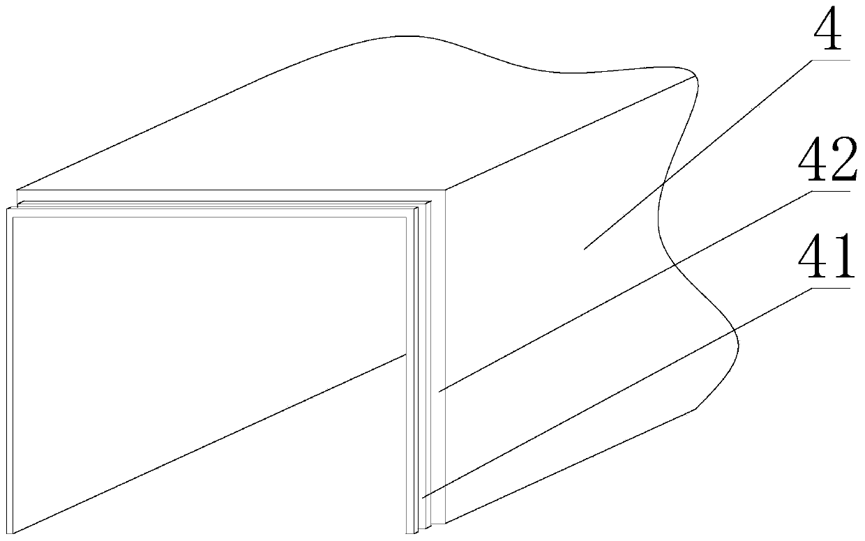
[0036] This embodiment provides a specific implementation solution on the basis of the technical solution provided in Embodiment 1, such as figure 2 As shown, because in this device, the single U-shaped card slot 4 is made too long and is not only inconvenient for the transportation of the U-shaped card slot 4, but also is not convenient for improving the versatility of the U-shaped card slot 4, so it is set as: each U-shaped card slot The two ends of groove 4 are all provided with connecting section 41, and in the two connecting sections 41 of U-shaped card groove 4, the external dimension of one connecting section 41 wherein is less than the external dimension of U-shaped card groove 4 middle sections, and the other connects The inner size of the section 41 is larger than the inner size of the middle section of the U-shaped slot 4 . In this scheme, the connecting ends at both ends of the U-shaped card slot 4 are used for the seamless overlap between the adjacent U-shaped ca...
PUM
 Abstract
Description
Claims
Application Information