Biomass gas burner

A gas burner and biomass technology, which is applied to gas fuel burners, burners, combustion methods, etc., can solve the problems of inability to burn biomass gas well and the calorific value of biomass gas is unstable, and achieve stable combustion conditions. , the effect of full combustion

Pending Publication Date: 2017-07-28
王夏飞
View PDF7 Cites 3 Cited by
  • Summary
  • Abstract
  • Description
  • Claims
  • Application Information

AI Technical Summary

Problems solved by technology

[0002] Biomass gas is burned through biomass burners. Due to the diversification of biomass, the calorific value of gas generated by gas fluctuates greatly, that is, the calorific value of biomass gas is in an unstable state, (calorific value in a Fluctuations within the range, different from the stable calorific value of natural gas), biomass gas is composed of various components, including carbon, carbon monoxide, hydrogen, methane, tar, wood sulfuric acid, etc., so the existing biomass burner cannot Intact burning biomass gas

Method used


Image

  • Biomass gas burner
  • Biomass gas burner
  • Biomass gas burner

Examples


Embodiment Construction

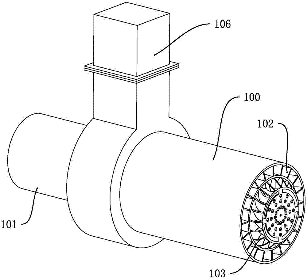
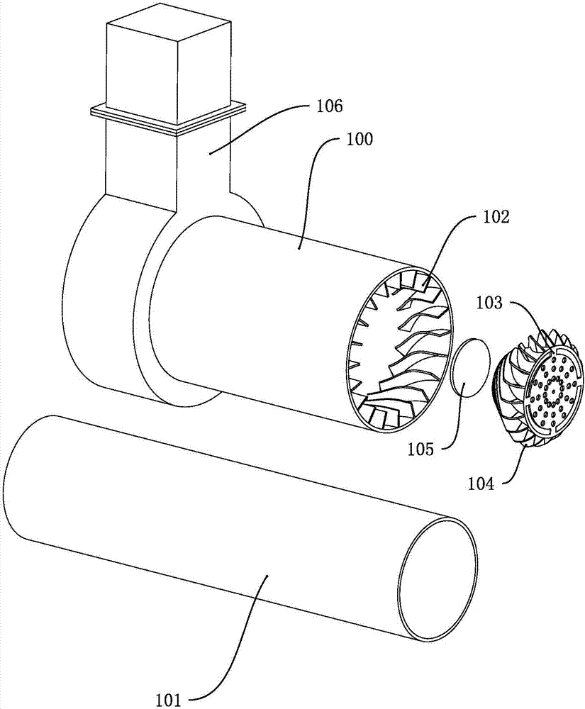
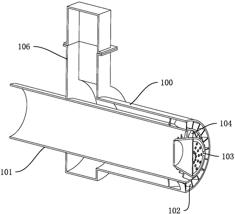
[0019] Such as Figure 1 to Figure 3 As shown, a biomass gas burner includes an air duct 100 for introducing air, a combustion tube 101 whose rear end is connected to an external biomass gas delivery pipeline, and a burner 103 located in the front end of the combustion tube 101 . The front end inner wall of the air guide pipe 100 is provided with a first guide vane 102, and the front end of the combustion pipe 101 extends into the air guide pipe 100 at the rear end of the combustion pipe 101 and there is a gap between the inner wall of the air guide pipe 100. The combustion pipe 101 It is sealed and connected with the rear end of the air guide pipe 100, and the front end of the combustion pipe 101 is flush with the front end of the air guide pipe 100; the shape of the burner 103 is a cone shape, a truncated cone, and the outer wall of the burner 103 is provided with a second flow guide The vanes 104, the first guide vanes 102 and the second guide vanes 104 form a guide air cha...


PUM


Abstract

The invention discloses a biomass gas burner. The biomass gas burner comprises an air guide pipe, a combustion pipe and a gas log which is arranged in the front end of the combustion pipe. First guide vanes are arranged on the inner wall of the front end of the air guide pipe. The front end of the combustion pipe stretches into the air guide pipe at the rear end of the combustion pipe, and a gap is reserved between the front end of the combustion pipe and the inner wall of the air guide pipe. The combustion pipe is connected with the rear end of the air guide pipe in a sealing mode, and the front end of the combustion pipe is flush with the front end of the air guide pipe. The gas log is in a frustum shape, and second guide vanes are arranged on the outer wall of the gas log. The first guide vanes and the second guide vanes form a flow guide air duct used for mixing air and biomass gas. The biomass gas burner has the advantages that the biomass gas and the air are mixed at the front end of the combustion pipe, the first guide vanes and the second guide vanes form the flow guide air duct, the flow guide air duct can make the air and the biomass gas be fully and evenly mixed, and therefore the combustion condition is more stable, and combustion is made more sufficient.

Description

technical field [0001] The invention relates to the technical field of burners, in particular to a biomass gas burner. Background technique [0002] Biomass gas is burned through biomass burners. Due to the diversification of biomass, the calorific value of gas gas has great fluctuations, that is, the calorific value of biomass gas is in an unstable state, (calorific value in a Fluctuations within the range, different from the stable calorific value of natural gas), biomass gas is composed of various components, including carbon, carbon monoxide, hydrogen, methane, tar, wood sulfuric acid, etc., so the existing biomass burner cannot Burn biomass gas intact. Contents of the invention [0003] The purpose of the present invention is to solve the deficiencies of the prior art and provide a biomass gas burner. [0004] A kind of technical scheme of the present invention: [0005] A biomass gas burner, comprising an air guide pipe for introducing air, a combustion pipe whose...

Claims


Application Information

Patent Timeline
Patent Type & Authority Applications(China)
IPC IPC(8): F23D14/24F23D14/70F23D14/46F23D14/48
CPCF23D14/24F23D14/46F23D14/48F23D14/70F23D2900/14
Inventor 王夏飞陈奕佑
Owner 王夏飞
Why Eureka
Try Eureka