
A display panel and a method for manufacturing the same

A technology for a display panel and a manufacturing method, which is applied to instruments, semiconductor devices, optics, etc., can solve the problems of high photoconductivity, large leakage current, etc., and achieve the effect of good display effect, reduced impact, and improved display quality.

Inactive Publication Date: 2017-07-28
HKC CORP LTD +1
View PDF5 Cites 4 Cited by
  • Summary
  • Abstract
  • Description
  • Claims
  • Application Information

AI Technical Summary

Problems solved by technology

[0004] At present, the display industry is gradually developing towards higher definition, higher resolution, and thinner. Therefore, the number of pixels per inch (Pixels Per Inch, PPI) in the display panel design of many existing high-end products is getting higher and higher. The photoconductivity of the semiconductor layer on the active switch is relatively high, so there will be a large leakage current under light irradiation.

Method used


Image

  • A display panel and a method for manufacturing the same
  • A display panel and a method for manufacturing the same
  • A display panel and a method for manufacturing the same

Examples


Embodiment Construction

[0041] Specific structural and functional details disclosed herein are representative only and for purposes of describing example embodiments of the present invention. This invention may, however, be embodied in many alternative forms and should not be construed as limited to only the embodiments set forth herein.

[0042] In describing the present invention, it is to be understood that the terms "central", "lateral", "upper", "lower", "left", "right", "vertical", "horizontal", "top", The orientation or positional relationship indicated by "bottom", "inner", "outer", etc. is based on the orientation or positional relationship shown in the drawings, and is only for the convenience of describing the present invention and simplifying the description, rather than indicating or implying the referred device Or components must have a particular orientation, be constructed and operate in a particular orientation and therefore should not be construed as limiting the invention. In addi...


PUM


Abstract

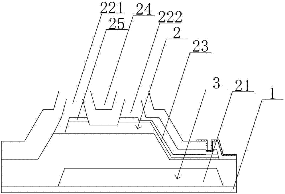
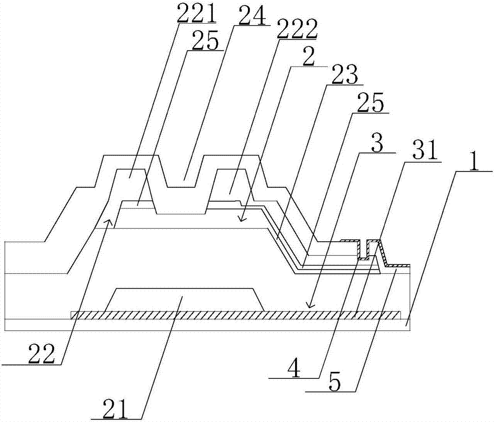
The invention provides a display panel which comprises a substrate and an active switch arranged on the substrate. A shading layer is arranged between the active switch and the substrate and the active switch comprises a semiconductor layer. The shading layer covers the semiconductor layer completely. The shading layer can effectively reduce the illumination of backlight on the semiconductor layer, so that illumination light leak currents can be further reduced, the influence of light leak currents on image display can be effectively reduced and the display quality of the display panel can be further improved.

Description

technical field [0001] The present invention relates to the field of display technology, and more specifically, to a display panel and a manufacturing method thereof. Background technique [0002] The display has many advantages such as thin body, power saving, no radiation, etc., and has been widely used. Most of the displays currently on the market are backlight displays, which include a display panel and a backlight module. The working principle of the display panel is to place liquid crystal molecules between two parallel substrates, and apply a driving voltage on the two substrates to control the rotation direction of the liquid crystal molecules, so as to refract light from the backlight module to generate images. [0003] Among them, Thin Film Transistor-Liquid Crystal Display (TFT-LCD) has gradually occupied a dominant position in the display field due to its low power consumption, excellent picture quality, and high production yield. Similarly, a thin film transis...

Claims


Application Information

Patent Timeline
Patent Type & Authority Applications(China)
IPC IPC(8): G02F1/1335G02F1/1333H01L27/12
CPCH01L27/1214H01L27/1259G02F1/1333G02F1/133512G02F1/136209G02F1/1368H01L29/78633H01L29/42384H01L29/4908H01L27/1288H01L29/78669G02F1/136236H01L27/124H01L27/1262
Inventor 简重光
Owner HKC CORP LTD
Learn More