Unlock instant, AI-driven research and patent intelligence for your innovation.

Radio frequency receiver

A radio frequency receiver and radio frequency technology, applied in radio frequency amplifiers, high frequency amplifiers, amplifiers, etc., can solve the problems of large power consumption and large size

Active Publication Date: 2017-07-28
MEDIATEK INC
View PDF2 Cites 3 Cited by
  • Summary
  • Abstract
  • Description
  • Claims
  • Application Information

AI Technical Summary

Problems solved by technology

Also, to suppress the mismatch impairments introduced by passive mixing, the mixer size must be large to reduce the need for adding additional mixer switch impedance to the required low impedance path
Unfortunately, larger mixer sizes require larger local oscillator (LO) drivers, and thus result in larger power consumption

Method used


Image

  • Radio frequency receiver
  • Radio frequency receiver
  • Radio frequency receiver

Examples


Embodiment Construction

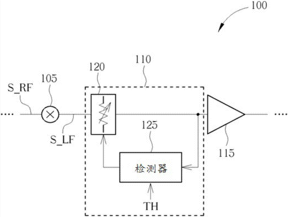
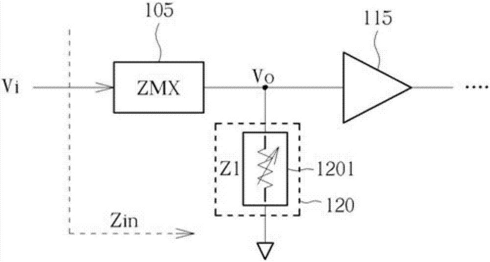
[0024] For low-power or ultra-low-power receiver designs, a passive mixer is a better choice because it consumes less current. In order to maintain high linearity and impedance matching of the receiver, conventionally passive mixers preferably have low impedance when enabled and high impedance when disabled. To achieve this, passive mixers are typically sized to provide low impedance when enabled, and are typically used with TIAs that have low output impedance. However, due to the large size of the passive mixer and the relation of the TIA, the power consumption becomes high.

[0025] In an embodiment of the present invention, the objectives are (1) to reduce power consumption, (2) to configure the input impedance and output impedance of the passive mixer to be high impedance, so that the receiver front end can interface with the high input impedance baseband circuit. matching, and (3) maintaining linearity (linearity performance is better than that of receiver designs known ...


PUM


Abstract

A radio frequency receiver is provided. The receiver can be employed in a low power (or ultra-low power) receiver architecture to generate a baseband signal or an intermediate frequency signal. In addition, the receiver includes capabilities of gain control to provide different gain settings as well as providing better / improved impedance matching control.

Description

[0001] 【Technical field】 [0002] The present application relates generally to a receiver scheme, and more particularly to a radio frequency receiver front-end. [0003] 【Background technique】 [0004] In general, a conventional receiver includes a Low Noise Amplifier (LNA) for improving the signal-to-noise ratio, a mixer for frequency conversion, and a low-pass filter for channel selection and filtering out unwanted signals. The linearity of conventional receivers is usually limited by the LNA and mixer. To achieve high linearity, a conventional solution may configure the output impedance of the LNA to be low impedance, and pair it with a passive mixer with good linearity characteristics. In order to achieve low output impedance, a conventional solution can use a transimpedance amplifier (transimpedance amplifier, TIA), wherein the TIA has a low input impedance at the baseband, and the low input impedance can be converted to RF frequency. Additionally, to suppress the misma...

Claims


Application Information

Patent Timeline
IPC IPC(8): H04B1/16H03G3/30H03F3/19
CPCH03F3/19H03F2200/222H03F2200/294H03F2200/451H03G3/3036H04B1/1638H03D7/1491H03G3/3052H04B1/40
Inventor 尼瑞克方房敬良薛岱黃亮景
Owner MEDIATEK INC
Features
  • R&D
  • Intellectual Property
  • Life Sciences
  • Materials
  • Tech Scout
  • Unparalleled Data Quality
  • Higher Quality Content
  • 60% Fewer Hallucinations
Learn More