
An intelligent inflow control device and method

A gas device and intelligent technology, which is applied in the field of devices to improve the gas flow control ability of gas cap reservoirs and gas injection production reservoirs, can solve the problems of not being able to effectively close the flow channel after the gas breaks through the reservoir, and avoid production safety problems , Improve the effect of displacement efficiency

Active Publication Date: 2019-05-07
SOUTHWEST PETROLEUM UNIV
View PDF5 Cites 0 Cited by
  • Summary
  • Abstract
  • Description
  • Claims
  • Application Information

AI Technical Summary

Problems solved by technology

[0007] The present invention aims at the problem that the existing AICD cannot effectively close the flow channel after the gas breaks through the reservoir, and provides an intelligent inflow control device

Method used


Image

  • An intelligent inflow control device and method
  • An intelligent inflow control device and method
  • An intelligent inflow control device and method

Examples


Embodiment Construction

[0022] The present invention will be further described below in conjunction with the accompanying drawings.

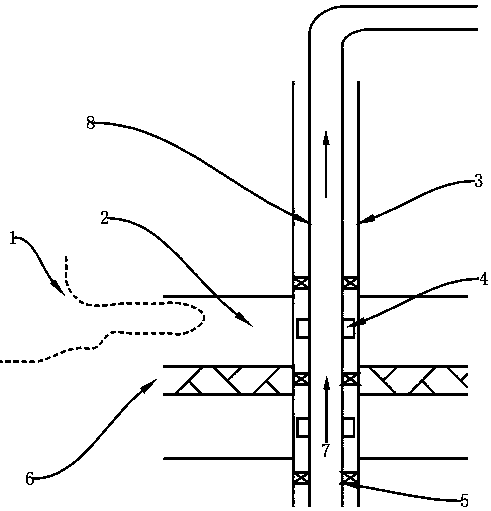
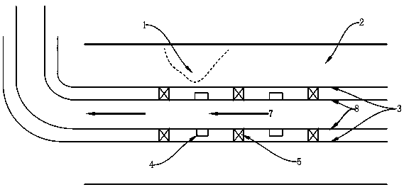
[0023] figure 1 It is a working partial schematic diagram of the device installed in a vertical shaft. Casing 3 and tubing 8 vertically pass through oil layer 2 and isolation layer 6, while casing 3 and tubing 8 will form an annular space, and packer 5 is added in the annular space, and the position of packer 5 is directly opposite to isolation layer6. The casing 3 is perforated to communicate the oil layer 2 with the annular space. The fluid in the oil layer 2 reaches around the wellbore, enters the annular space through the perforation hole, flows into the tubing 8 through the intelligent inflow control device 4, and reaches the surface along the flow direction 7 to be produced.

[0024] For ease of understanding, figure 1 Only one gas cone interface 1, one isolation layer 6, one oil layer 2, and one intelligent inflow control device 4 are marked, that is, the in...


PUM


Abstract

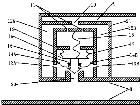
The invention discloses an intelligent inflow gas control device which mainly comprises a flow chamber, pressure guide holes, inlet oil nozzles, a packet, a sawtooth-shaped movable component and turn-off structures. The maximum quantity Q <max> of gas which is allowed to flow through the inlet oil nozzles can be set according to actual production requirements on oil wells. The intelligent inflow gas control device can normally work when the quantity Q of the gas which flows through the inlet oil nozzles does not exceed the set maximum quantity Q <max> of the gas; the intelligent inflow gas control device is turned off when the quantity Q of the gas reaches the set maximum quantity Q <max> of the gas, and fluid is no longer allowed to flow through the intelligent inflow gas control device. A working principle for the intelligent inflow gas control device includes that the gas can critically flow in the inlet oil nozzles when the flow rates of the gas in the inlet oil nozzles reach the maximum quantity Q <max> of the gas; ratios of front-end pressures P1 to rear-end pressures P2 of the inlet oil nozzles are critical pressure ratios, and the intelligent inlet gas control device can be turned off under the control of the critical pressure ratios. The intelligent inflow gas control device has the advantages that the intelligent inflow gas control device can be applied to gas-top reservoirs and gas injection production straight wells, horizontal wells and inclined wells, specified gas quantity exceeding gas flow channels can be timely closed, accordingly, economic benefits of oil fields can be increased, and the recovery ratios of oil reservoirs can be increased.

Description

technical field [0001] The invention relates to the technical field of oil well gas control. More specifically, the present invention relates to apparatus and methods that can be used at least to improve gas flow control capabilities in gas cap reservoirs and gas injection production reservoirs. Background technique [0002] At present, most of the domestic oil fields that can be exploited by self-spraying have been developed, leaving some oil reservoirs that are difficult to exploit. Most of these oil reservoirs need to be developed by injecting energy, such as injecting gas. During the process of gas injection into the reservoir, due to the large difference in physical properties between gas and formation crude oil (such as low gas density and viscosity), gas flows more easily than formation crude oil. Further, gas cones and gas channeling occur in the oil layer, and it is easier to flow into the wellbore and be produced than crude oil. While a large amount of gas is bei...

Claims


Application Information

Patent Timeline
Patent Type & Authority Patents(China)
IPC IPC(8): E21B43/12
CPCE21B43/12
Inventor 李海涛崔小江葛梁茜子李斌斌刘权王坤赵静
Owner SOUTHWEST PETROLEUM UNIV
Learn More