
Multichannel magnetic resonance radio frequency transmission method and multichannel magnetic resonance radio frequency transmission device

A radio frequency emission and magnetic resonance technology, applied in magnetic resonance measurement and other directions, can solve the problems of inability to achieve independent adjustment of modulation signals, high implementation difficulty and cost, phase and amplitude differences, etc., it is easy to achieve the number of channels, and reduce implementation difficulty and cost. , the effect of reducing complexity and cost

Active Publication Date: 2017-08-01
PEKING UNIV
View PDF6 Cites 7 Cited by
  • Summary
  • Abstract
  • Description
  • Claims
  • Application Information

AI Technical Summary

Problems solved by technology

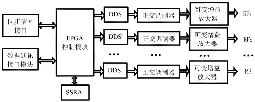
[0004] At present, the multi-channel RF transmission method mainly has the following two implementation methods: one is the implementation method of expanding a single-channel RF signal into a multi-channel RF signal, such as figure 1 As shown, this scheme uses a power divider to divide a single RF transmission source into multiple RF signals, and then uses a phase shifter and an attenuator to adjust the phase and amplitude of each signal, but this scheme cannot achieve independent modulation of each channel Modulation, all output signals are modulated in the same way, differing only in phase and amplitude
Another implementation method using multiple independent DDS circuits to obtain multiple radio frequency signals, such as figure 2 As shown, this scheme uses multiple parallel DDS chips and signal modulation circuits to realize the generation and modulation of radio frequency signals. Since each signal uses a dedicated DDS chip and signal modulation circuit, it can realize independent modulation of each signal , but the design complexity of this scheme is high, and the implementation difficulty and cost are high

Method used


Image

  • Multichannel magnetic resonance radio frequency transmission method and multichannel magnetic resonance radio frequency transmission device
  • Multichannel magnetic resonance radio frequency transmission method and multichannel magnetic resonance radio frequency transmission device
  • Multichannel magnetic resonance radio frequency transmission method and multichannel magnetic resonance radio frequency transmission device

Examples


Embodiment 1

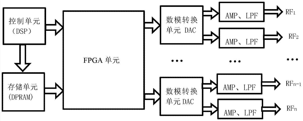
[0058] This embodiment adopts the multi-channel magnetic resonance radio frequency transmission method provided by the present invention to realize four-channel radio frequency transmission, which can simultaneously transmit four radio frequency signals whose phase, frequency and amplitude can be independently adjusted. Figure 6 The physical circuit diagram of the four-channel radio frequency transmission method provided in this embodiment. The following combination image 3 and Figure 4 The specific implementation of the present invention is described in detail.

[0059] A) the DSP chip in the present embodiment is a control unit, such as image 3 As shown, the phase, frequency, and amplitude parameters of the two carrier signals are output to the DPRAM, and the waveform files and control signals of the two modulation signals are output to the FPGA unit at the same time.

[0060] B) if image 3 As shown, the FPGA unit in this embodiment is designed and developed by usin...


PUM


Abstract

The invention discloses a multichannel magnetic resonance radio frequency transmission method and a multichannel magnetic resonance radio frequency transmission device. Firstly, a FPGA (Field-Programmable Gate Array) is adopted to realize a DDS (Direct Digital Synthesizer) function and radio frequency waveform signal modulation; then, through an independent and high-performance DAC (Digital to Analog Converter) chip, multiple paths of radio frequency pulse signals with phase, frequency and amplitude adjustable independently can be outputted parallelly. Based on the FPGA and the DAC chip, the FPGA is used for realizing the DDS function and the radio frequency signal modulation on the multiple paths of signals, the multiple paths of radio frequency pulse signals with phase, frequency and amplitude adjustable independently can then be outputted parallelly through the high-performance DAC, a uniform radio frequency field is provided, and the quality of the high-field magnetic resonance signals is further improved. The problem that the existing technical scheme can not realize independent adjustment on each channel of signals can be solved effectively, and the complexity and the cost are reduced.

Description

technical field [0001] The invention relates to the technical field of magnetic resonance imaging, in particular to a multi-channel magnetic resonance radio frequency transmission method and device. Background technique [0002] The radio frequency signal transmitter is one of the important components of the nuclear magnetic resonance imaging spectrometer. It generates radio frequency signals whose frequency, phase and amplitude can be adjusted quickly. magnetic resonance signals. With the popularization of nuclear magnetic resonance imaging systems in our country, high-field superconducting magnetic resonance systems are becoming more and more important, because higher field strength means better image quality and more accurate inspection results, especially in nerves, bone joints and blood vessels In terms of imaging, high-field magnetic resonance has unique advantages. [0003] High-field magnetic resonance imaging equipment has the advantages of faster scanning speed, ...

Claims


Application Information

Patent Timeline
Patent Type & Authority Applications(China)
IPC IPC(8): G01R33/32
CPCG01R33/32
Inventor 王为民何刚姜佳岐
Owner PEKING UNIV
Learn More