
Energy storage apparatus and method for determining misuse of energy storage device

A technology for electric storage components and electric storage devices, which is applied in the direction of electric devices, electrical components, circuit devices, etc., and can solve problems such as overcharging of electric storage components and achieve the effect of preventing bad conditions

Active Publication Date: 2017-08-01
GS YUASA INT LTD
View PDF9 Cites 7 Cited by
  • Summary
  • Abstract
  • Description
  • Claims
  • Application Information

AI Technical Summary

Problems solved by technology

Therefore, for example, in a vehicle for a lead-acid battery equipped with a lead-acid battery, an electric storage element (secondary battery) having a charging voltage lower than that of the lead-acid battery is erroneously mounted, and when the electric storage element is charged in the same manner as the lead-acid battery , the storage element becomes overcharged, causing a bad situation

Method used


Image

  • Energy storage apparatus and method for determining misuse of energy storage device
  • Energy storage apparatus and method for determining misuse of energy storage device
  • Energy storage apparatus and method for determining misuse of energy storage device

Examples


Embodiment approach 1

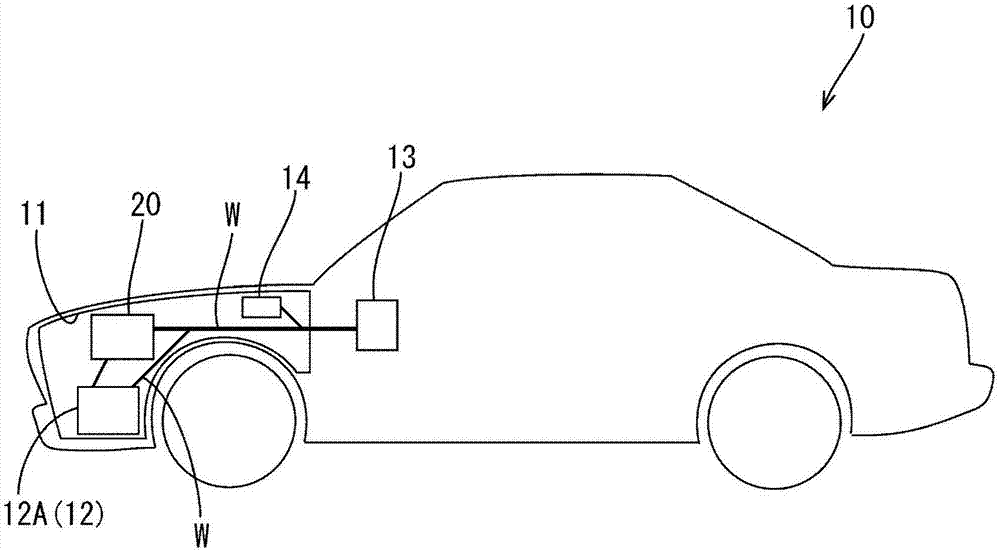
[0058] refer to Figure 1 to Figure 8 Embodiment 1 in which the technique disclosed in this specification is applied to a vehicle 10 such as an automobile will be described.

[0059] The electricity storage element of the present embodiment is not particularly limited as long as it is a chargeable electricity storage element. The power storage element may be, for example, a secondary battery or a capacitor. When a secondary battery is used as the power storage element, the power storage device of the present invention is a storage battery device. Hereinafter, as an example of an embodiment, a storage battery device using a secondary battery as a storage element will be described.

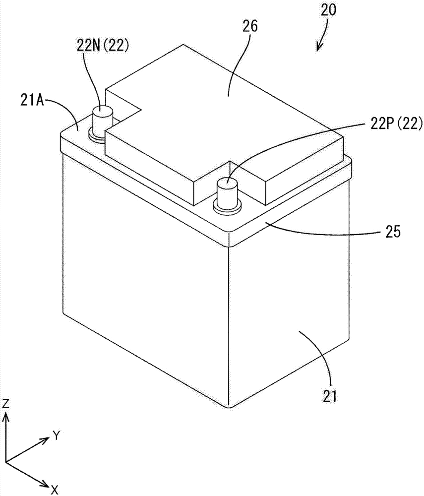
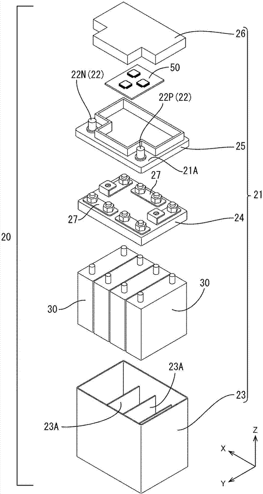
[0060] like figure 1 As shown, the vehicle 10 of this embodiment is configured to include: a starter motor for starting the engine installed in the engine room 11, a vehicle load 12 such as electrical equipment, a battery device 20 connected to the vehicle load 12, and a vehicle load 12 and a bat...

Embodiment approach 2

[0114] Next, refer to Figure 10 Embodiment 2 will be described.

[0115] Embodiment 2 changes the configuration of the use prohibition process in Embodiment 1, and since the same configuration, operation, and effect as Embodiment 1 overlap, description thereof will be omitted. In addition, the same code|symbol is used for the same structure as Embodiment 1.

[0116] The use prohibition process in Embodiment 2 is configured so that the timing when the current interrupter 81 is turned off and the timing when the auxiliary current interrupter 84 is turned off are independent.

[0117] Below, refer to Figure 10 The usage prohibition process of the secondary battery 30 in this embodiment will be described. In addition, similarly to Embodiment 1, in the following description, the detection of the voltage by the voltage detection circuit 70 of the secondary battery 30 and the detection of the current by the current detection part 67 are performed constantly or periodically.

[...


PUM


Abstract

The invention provids an energy storage apparatus and a method for determining misuse of an energy storage device for preventing adverse status in a secondary battery that is mounted on a vehicle. The energy storage apparatus is mounted on a vehicle and includes: an energy storage device which is connected to a vehicle load and a vehicle power generator; a current interrupt device that causes the energy storage device and the vehicle load as well as the energy storage device and the vehicle power generator to be in a conduction state or in an interruption state; a voltage detection unit that detects voltage of the energy storage device; and a control unit. The control unit executes: a switching instruction process in which, when determining that the electric storage device will reach an overcharge state on the basis of the voltage, the control unit issues an interruption switching instruction to the current interrupt device; and an interruption maintaining process in which, when the number of times of the switching instruction process exceeds a predetermined value, the control unit issues an instruction to maintain the interruption state.

Description

technical field [0001] The technique disclosed in this specification relates to a method of judging improper use of an electric storage device and an electric storage element. Background technique [0002] For example, Japanese Patent Application Laid-Open No. 2014-225942 is known as an electric storage system for engine starting of a vehicle. In this storage battery system, instead of a lead storage battery, an electrical storage element (secondary battery) having a charging voltage lower than that of a lead storage battery, such as a nickel metal hydride battery or a lithium ion battery, is used. [0003] prior art literature [0004] patent documents [0005] Patent Document 1: Japanese Patent Laid-Open No. 2014-225942 [0006] However, although the control method of this storage battery system is different from that of a lead storage battery, since it is mounted on a vehicle, the external shape and the shape of a communication connector are made into the same shape as...

Claims


Application Information

Patent Timeline
Patent Type & Authority Applications(China)
IPC IPC(8): H02J7/00H01M10/42B60L11/18B60L3/00
CPCB60L58/12B60L3/0046H01M10/4257H02J7/0031H01M2010/4271H02J7/00302H01M10/482H01M10/052H01M10/425B60R16/033H02J2310/40H02J2310/46Y02E60/10Y02T10/70H02J7/0025B60R16/04
Inventor 白石刚之中村将司中本武志
Owner GS YUASA INT LTD
Learn More