Mechanical-air cavity-electronic combined generalized resonant pneumatic power generation device
A technology of power generation device and air cavity, which is applied in the direction of electromechanical devices, electric components, electrical components, etc., can solve problems such as small electric energy
- Summary
- Abstract
- Description
- Claims
- Application Information
AI Technical Summary
Problems solved by technology
Method used
Image

Examples
Embodiment 1
[0065] A mechanical-air cavity-electronic combined generalized resonant pneumatic power generation device installed to the socket of the electronic device shell by aviation insertion.
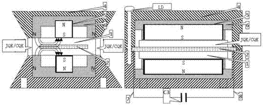
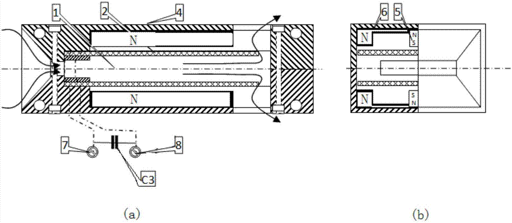
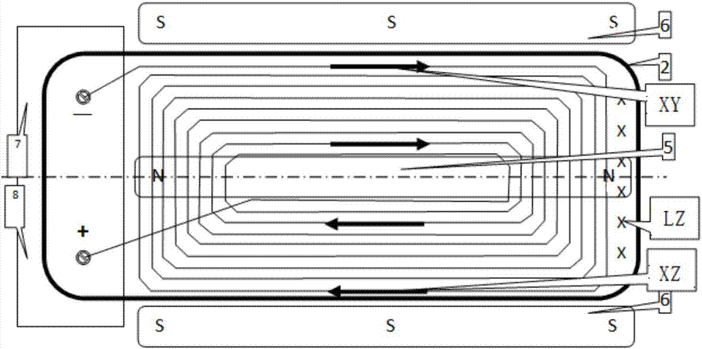
[0066] Contains an air chamber 1 arranged in the flow field along the direction of gas flow, with an aerodynamic generalized resonance frequency of FQ, and is partially fixed on the air chamber housing 4, located on the only way of air flow, and contains an inductance of L The PCB printed circuit board 2 of the printed circuit coil whose mechanical generalized resonant frequency is FP, and the resonant capacitor C3 connected in parallel with the two output connections 7 and 8 of the PCB printed circuit coil, are arranged in the air cavity and printed parallel to the PCB. The circuit board 2 and the magnetic field formed by the permanent magnet 5 and the pole piece 6 perpendicular to the moving direction of the printed circuit coil, output AC current and voltage from the two output connections 7 ...
Embodiment 2
[0069] The mechanical-gas cavity-electronic joint generalized resonant pneumatic power generation device fixed on the shell of the electronic device.
[0070] Contains an air chamber 1 arranged in the flow field along the direction of gas flow, with an aerodynamic generalized resonance frequency of FQ, and is partially fixed on the air chamber housing 4, located on the only way of air flow, and contains an inductance of L The PCB printed circuit board 2 of the printed circuit coil, whose generalized mechanical resonant frequency is FP, and the resonant capacitor C3 connected in parallel with the two output terminals 7 and 8 of the PCB printed circuit coil, are arranged in the air cavity and parallel to the printed circuit board of the PCB. The circuit board 2 and the magnetic field formed by the permanent magnet 5 and the pole shoe 6 perpendicular to the moving direction of the printed circuit coil, output AC current and voltage from the two output terminals 7 and 8 of the prin...
Embodiment 3
[0074] Mechanical generalized resonance PCB fixed at both ends of the mechanical - air cavity - electronic joint generalized resonance pneumatic power generation device.
[0075] In order to overcome the drawbacks of the mechanical generalized resonance PCB printed circuit board 2 in the first and second embodiments, the vibration amplitude is too large under the condition of strong wind due to the single-end fixation, and the fatigue fracture of the air cavity shell and the fixed part of the PCB, the present embodiment proposes "Mechanical-air cavity-electronic combined generalized resonance pneumatic power generation device with mechanical generalized resonance PCB fixed at both ends", such as Figure 7 shown.
[0076] Contains an air chamber 1 arranged in the flow field along the direction of gas flow and has an aerodynamic generalized resonance frequency of FQ, and is partially fixed on the air chamber housing 4, located on the only way for the air flow, and contains an in...
PUM
 Abstract
Description
Claims
Application Information
 - R&D
- Intellectual Property
- Life Sciences
- Materials
- Tech Scout
- Unparalleled Data Quality
- Higher Quality Content
- 60% Fewer Hallucinations
Browse by: Latest US Patents, China's latest patents, Technical Efficacy Thesaurus, Application Domain, Technology Topic, Popular Technical Reports.
© 2025 PatSnap. All rights reserved.Legal|Privacy policy|Modern Slavery Act Transparency Statement|Sitemap|About US| Contact US: help@patsnap.com