Fractal structure on satellite surface

A fractal structure and satellite technology, applied in the field of satellite thermal control, to achieve the effect of increasing radiation heat transfer capacity

Inactive Publication Date: 2017-08-04
SHANGHAI ENG CENT FOR MICROSATELLITES
View PDF4 Cites 0 Cited by
  • Summary
  • Abstract
  • Description
  • Claims
  • Application Information

AI Technical Summary

Problems solved by technology

In the current thermal control system of micro-satellites, the traditional research focus is mostly on the heat transfer system and the study of star surface materials, and it is often easy to ignore the influence of satellite surface morphology and structure on the star's heat transfer capability

Method used


Image

  • Fractal structure on satellite surface
  • Fractal structure on satellite surface
  • Fractal structure on satellite surface

Examples


Embodiment Construction

[0017] Hereinafter, the spirit and essence of the present invention will be further elaborated in conjunction with the drawings and embodiments.

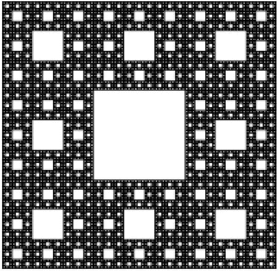
[0018] figure 1 A schematic diagram showing the basis of the fractal structure of the present invention applied to the surface of a microsatellite, a sierpinski (Sierpinski) carpet pattern. The pattern has typical fractal characteristics and obvious self-similarity. Applying this pattern to the design of the surface of micro-satellites can regularly design and manufacture irregular surface structure features;

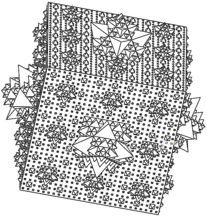
[0019] Such as figure 2 As shown, in this embodiment, the satellite body is a cube structure, and the fractal structure is formed on any one or more surfaces of the satellite. The fractal structure can have one or more levels. The first-order fractal structure includes: classifying at least one surface of the cube structure to form at least nine second-level squares with equal areas, and a raised first-level regular quad...


PUM


Abstract

The invention discloses a fractal structure on a satellite surface. A satellite body is a cube structure, and Sierpinski carpet patterns are created on any surface of the satellite body. The fractal structure comprises regular square pyramid protrusions taking squares in the middle of the Sierpinski carpet patterns as bottom surfaces.

Description

technical field [0001] The invention relates to the field of satellite thermal control, in particular to the satellite surface fractal structure. Background technique [0002] Microsatellites are currently one of the three research hotspots and development frontiers in the aerospace field, and are favored by the international aerospace community. The characteristics of small size, light weight, and high heat flux of microsatellites make the internal spaceborne equipment of microsatellites increasingly diverse and the working mode increasingly complicated; the uncertainty of the environment for performing space missions; and the reliability of microelectronic devices It is very sensitive to temperature, and the reliability will drop by 5% for every 1°C increase in device temperature at the level of 70-80°C. All of the above factors pose new challenges to the design of the microsatellite thermal control system. [0003] At present, the research on the thermal control system ...

Claims


Application Information

Patent Timeline
Patent Type & Authority Applications(China)
IPC IPC(8): B64G1/10
CPCB64G1/10
Inventor 张晓峰梁庄典王刚侯玉鑫谢余
Owner SHANGHAI ENG CENT FOR MICROSATELLITES
Why Eureka
Try Eureka