Pressurization oil tank for injection molding machine

A pressurized oil tank and injection molding machine technology, applied in the direction of oil supply tank devices, mechanical equipment, fluid pressure converters, etc., can solve the problems of self-priming of oil pumps that cannot meet the standards, achieve optimized oil suction pipe diameter, reduce noise, and simple and reasonable structure Effect

Inactive Publication Date: 2017-08-04
GUANGDONG YIZUMI HIGH SPEED PACKAGING SYST COMPANY
View PDF8 Cites 2 Cited by
  • Summary
  • Abstract
  • Description
  • Claims
  • Application Information

AI Technical Summary

Problems solved by technology

[0003] The purpose of the present invention is to provide a pressurized oil tank for injection molding machines that can solve the problem that the self-priming of oil pumps in plateau areas cannot meet the standard, improve the oil-absorbing environment, prolong the service life of the pump, and optimize the size of the oil-absorbing pipe diameter, so as to overcome the existing technology. inadequacies in

Method used


Image

  • Pressurization oil tank for injection molding machine
  • Pressurization oil tank for injection molding machine

Examples


Embodiment Construction

[0017] The present invention will be further described below with reference to the drawings and embodiments.

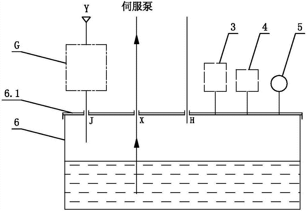
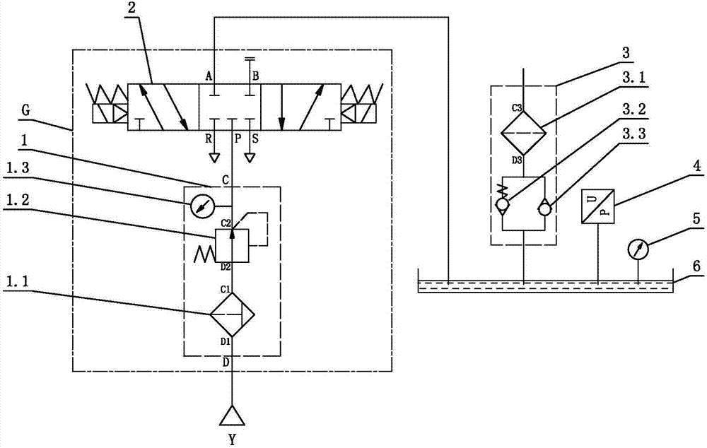
[0018] See figure 1 with figure 2 , The pressurized fuel tank for the injection molding machine includes a tank 6 for storing oil. The top of the tank 6 is provided with an air inlet J, an oil suction port X and an oil return port H; the air inlet J is connected with an air supply device G , The suction port X is connected to the suction end of the servo pump; the air supply device G includes a pneumatic two-piece 1 and a pneumatic reversing valve 2, and the air inlet J is connected to an external compressed air source through the pneumatic reversing valve 2 and the pneumatic two-piece 1 in turn Y. In this structure, the air supply device is provided to make the air pressure inside the box 6 greater than the outside air pressure, thereby improving the pressure of the oil pump suction port, thereby ensuring reliable operation of the hydraulic system of the injection mol...


PUM


Abstract

A pressurization oil tank for an injection molding machine comprises an oil tank for oil storage. The tank body is provided with an air inlet, an oil suction opening and an oil return opening. The air inlet communicates with an air supply device, and the oil suction opening communicates with the oil suction end of a servo pump. The air supply device comprises a pneumatic dual linkage part and a pneumatic reversing valve, and the air inlet communicates with an outside compressed air source sequentially through the pneumatic reversing valve and the pneumatic dual linkage part. The pressurization oil tank has the following beneficial effects that the structure is simple and reasonable, the air pressure in the oil tank is larger than the outside air pressure through the air supply device, the pressure of the oil suction opening of an oil pump is improved, and therefore it can be ensured that a hydraulic system of the injection molding machine reliably operates in plateau sections, the noise of the oil pump can be reduced, and the service life of the oil pump can be prolonged; the tank body in the structure is totally closed, and the cleanliness of oil can be effectively improved; and it can be ensured that self suction of the oil pump is smooth in the plateau sections, in addition, the oil suction pipe diameter can be optimized, and the functions of reasonable layout and structure optimization can be achieved.

Description

Technical field [0001] The invention relates to an injection molding machine, in particular to a pressurized fuel tank for the injection molding machine. Background technique [0002] In the prior art, injection molding machines all use atmospheric oil tanks, and the pumps mainly rely on external atmospheric pressure to suck oil. However, as the use environment changes or the layout of the hydraulic pipeline is restricted, in order to ensure the pressure of the suction port of the hydraulic pump, the suction pipe of the corresponding pump It will be very large or the machine cannot operate normally, especially for high-speed injection injection molding machines used at high altitudes. This type of injection molding machine has a large instantaneous flow during high-speed injection. How to ensure the pressure of the oil pump suction port has become a problem. Therefore, there are It is necessary to design an injection molding machine oil tank that can control the pressure. Summar...

Claims


Application Information

Patent Timeline
Patent Type & Authority Applications(China)
IPC IPC(8): F15B1/26F15B3/00F15B21/04
CPCF15B1/26F15B3/00F15B21/048
Inventor 李弘臻张元海方忠宝龚剑锋赖广龙梁继洪
Owner GUANGDONG YIZUMI HIGH SPEED PACKAGING SYST COMPANY
Why Eureka
Try Eureka