Integrated multifunctional pulling head water channel structure

A pull-out and multi-functional technology, applied in the field of faucets, can solve the problems of reducing production and assembly costs, difficulty in realizing flexible switching between large and small water flows, and high assembly costs, so as to reduce production and assembly costs, reduce product malfunctions, The effect of easy operation

Pending Publication Date: 2017-08-04
XIAMEN RUNNER IND CORP
View PDF0 Cites 1 Cited by
  • Summary
  • Abstract
  • Description
  • Claims
  • Application Information

AI Technical Summary

Problems solved by technology

The disadvantages in the above structure are: 1. When the front and rear switching components are connected by screws, the structure of the locking screw is complicated, and many processes are added to the assembly, resulting in high cost
2. When adopting the design of waterway welded sheet to realize the multi-functional structural design, although the structural cost and complexity of the welded sheet are better than that of the locking screw structure, there are still hidden dangers of water leakage such as poor welding and high assembly costs.
[0003] In addition, although the commonly used pull-out head has a multi-functional water outlet structure, there must be multiple water diversion channels in the structure to meet the multi-functional water outlet. One kind of water flow function, it is difficult to realize the flexible switching of large and small water flow, therefore, it is necessary to provide a waterway cavity with one part, so that the waterway function switching waterway cavity does not need to use multiple parts assembly or welding to realize , so as to reduce the poor product function caused by unstable assembly and welding processes, reduce the production and assembly costs of the water channel structure of the pull head, and the structure of the water channel of the pull head can realize the function of switching between large and small water flow in one water channel with one key

Method used


Image

  • Integrated multifunctional pulling head water channel structure
  • Integrated multifunctional pulling head water channel structure
  • Integrated multifunctional pulling head water channel structure

Examples


Embodiment 1

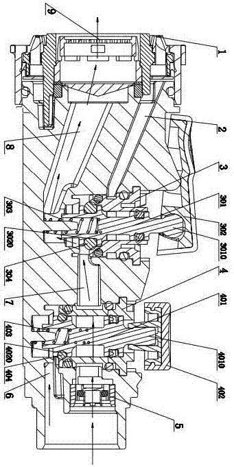
[0028] The invention discloses an integrated multifunctional drawing head waterway structure. refer to figure 1 , figure 1 It is a state schematic diagram of a state of the integrated multi-functional drawing head water channel structure according to the present invention, that is, the state of the first water outlet hole 9 with a small flow rate of water: the integrated multi-functional drawing head water channel structure includes a valve seat 10, The valve seat 10 is integrally formed, the valve seat 10 is provided with a main channel 7, and the main channel 7 is provided with a first channel 8, a second channel 2 and a flow increasing channel 6; The water channel 8 and the second water channel 2 are arranged at the water outlet of the main water channel 7, and a function switching mechanism 3 is arranged at the junction thereof, and the flow-increasing channel 6 is arranged near the water inlet of the main water channel 7, and the junction thereof A flow control mechanis...

Embodiment 2

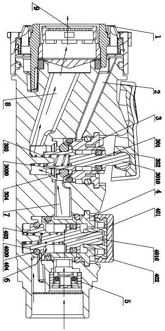
[0037] This embodiment is a state schematic diagram of another functional state of the integrated water channel structure of the pulling head according to the present invention, that is, the state of large flow of water from the first water outlet hole 9 . refer to figure 2 As shown, the difference between this embodiment and Embodiment 1 is that the flow control button 402 is in a pressed state in this state. At this time, the second valve rod 401 moves downward under the action of external force, compressing the second The second spring 403 at the bottom of the valve stem 401, at the same time, the second plug portion 4020 on the second valve stem 401 and the second sealing ring 404 on the second plug portion 4020 move downward, and then, the flow-increasing channel The connection between 6 and the main waterway 7 is changed from a blocking body to an on state. Obviously, in this state, the function switch button 302 is in the front pressed state consistent with the state i...

Embodiment 3

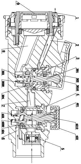
[0040] This embodiment is a state schematic diagram of another functional state of the integrated water channel structure of the pulling head according to the present invention, that is, the water outlet state of the second water outlet hole 1 with a small flow rate. refer to image 3 As shown, the difference between this embodiment and Embodiment 1 is that the front part of the function switching button 302 is lifted in this state, and the first valve rod 301 is lifted on the front part of the function switching button 302. Under the action of external force, the first spring 303 is compressed to move downward, the first plug portion 3020 and the first sealing ring 304 on the first valve rod 301 move downward, and the first water channel 8 and the Under the action of the first plug portion 3020 and the first sealing ring 304, the main water channel 7 is changed from the connected state to the blocked sealing state, and the second water channel 2 and the main water channel 7 a...


PUM


Abstract

The invention relates to the field of faucets, and discloses an integrated multi-functional drawing head water channel structure. The waterway structure of the pulling head includes a valve seat, the valve seat is integrally formed, a main waterway is arranged in the valve seat, and a first water distribution channel, a second water distribution channel and a flow-increasing channel are arranged on the main water channel, so that The first water distribution channel and the second water distribution channel are arranged at the water outlet of the main water channel, and a function switching mechanism is provided at the connection thereof, and the flow-increasing channel is provided near the water inlet of the main water channel, and the connection is provided with a flow control mechanism. The formation of the water channel cavity of the water channel structure of the pulling head according to the present invention requires only one part, and can realize the function of multiple water channels and the function of controlling the flow rate with one key, which reduces the production cost, provides stability, and has excellent assembly process complexity. It is applicable to the commonly used puller structure at present.

Description

technical field [0001] The invention relates to the field of faucets, and discloses an integrated multi-functional drawing head waterway structure. Background technique [0002] The kitchen pull-out head (or pull-out faucet) is installed on a fixed faucet seat, and after being pulled out, it is separated from the restriction of the fixed faucet seat, so that the kitchen pull-out head can be used flexibly in a larger range. At present, in order to achieve multi-functional operation, the pull-out head of the kitchen faucet on the market is usually designed by connecting the front and rear switching components with screws or adopting the design of the water channel welding piece to achieve a multi-functional structural design. The disadvantages in the above structure are: 1. When the front and rear switching components are connected by screws, the structure of the locking screw is complicated, and many processes are added in the assembly, resulting in high cost. 2. When adopti...

Claims


Application Information

Patent Timeline
Patent Type & Authority Applications(China)
IPC IPC(8): F16K11/22F16K27/02
CPCF16K11/22F16K27/0263
Inventor 陈磊李明
Owner XIAMEN RUNNER IND CORP
Why Eureka
Try Eureka