
Combustion chamber fuel nozzle device

A fuel nozzle and combustion chamber technology, which is applied in the aviation field, can solve problems such as easy scrapping of processing and unsatisfactory atomization effect of fuel nozzles in the combustion chamber, and achieve the effects of shortening the processing cycle, simple and compact structure, and reducing processing costs

Active Publication Date: 2017-08-04
AECC COMML AIRCRAFT ENGINE CO LTD
View PDF3 Cites 9 Cited by
  • Summary
  • Abstract
  • Description
  • Claims
  • Application Information

AI Technical Summary

Problems solved by technology

[0008] The technical problem to be solved by the present invention is to provide a combustion chamber fuel nozzle device in order to overcome the defect that the atomization effect of the combustion chamber fuel nozzle in the prior art is not ideal, and the processing is easy to be scrapped.

Method used


Image

  • Combustion chamber fuel nozzle device
  • Combustion chamber fuel nozzle device
  • Combustion chamber fuel nozzle device

Examples


Embodiment Construction

[0034] In order to make the above objects, features and advantages of the present invention more comprehensible, specific implementations of the present invention will be described in detail below in conjunction with the accompanying drawings.

[0035] Embodiments of the present invention will now be described in detail with reference to the accompanying drawings. Reference will now be made in detail to the preferred embodiments of the invention, examples of which are illustrated in the accompanying drawings. Wherever possible, the same numbers will be used throughout the drawings to refer to the same or like parts. In addition, although the terms used in the present invention are selected from well-known and commonly used terms, some terms mentioned in the description of the present invention may be selected by the applicant according to his or her judgment, and the detailed meanings thereof are set forth herein described in the relevant section of the description. Furtherm...


PUM


Abstract

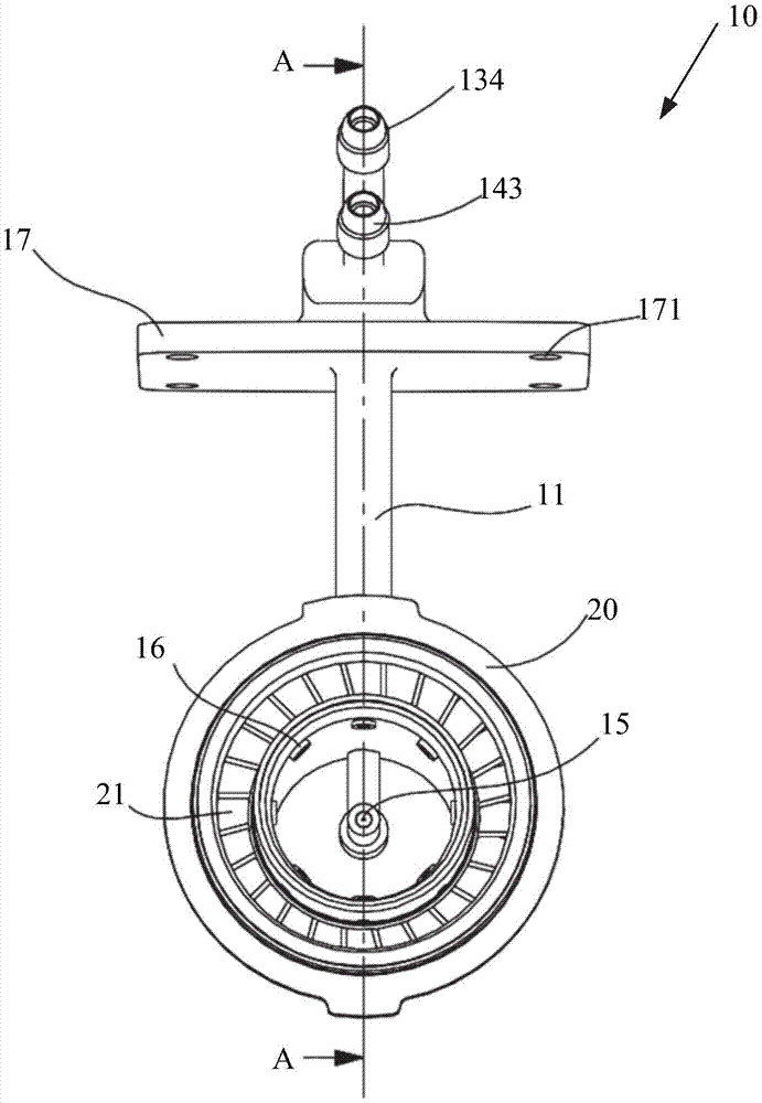
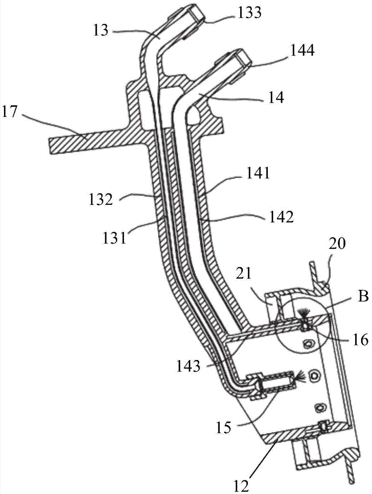
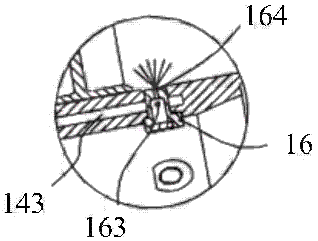
The invention provides a combustion chamber fuel nozzle device. The combustion chamber fuel nozzle device comprises a nozzle rod part and a fuel nozzle shell; a main combustion level oil line and a pre-combustion level oil line are arranged in the nozzle rod part; one end of the pre-combustion level oil line is connected into the fuel nozzle shell and provided with a pre-combustion level nozzle; one end of the main combustion level oil line is annularly distributed on the periphery of the fuel nozzle shell and provided with a plurality of main combustion level nozzles which are machined independently so that fuel oil in the main combustion level oil line can be ejected rotationally; and the fuel nozzle shell is connected with a main swirler and located at the outlet ends of the main combustion level nozzles and the outlet end of the pre-combustion level nozzle. According to the combustion chamber fuel nozzle device, the main combustion level nozzles are machined independently and then welded to the fuel nozzle shell, the oil injection mode of the main combustion level nozzles is adjusted, thus, the oil injection mode of the main combustion level nozzles is converted from the direct-injection mode into the centrifugal mode, the atomization effect is strengthened, mixing of fuel oil and air in a main combustion zone is facilitated, and finally, pollutant discharge of a combustion chamber is reduced.

Description

technical field [0001] The invention relates to the field of aviation, in particular to a combustion chamber fuel nozzle device. Background technique [0002] In the prior art, as the situation of environmental damage becomes more and more severe, the requirements for reducing pollution emissions of civil aeroengines are also getting higher and higher. The currently adopted CAEP6 (Committee on Aviation Environmental Protection) standard has very strict regulations on pollutant emissions, especially for nitrogen oxides (NO x ) pollution discharge requirements. However, the latest CAEP8 standard proposes that nitrogen oxides (NO x ) emissions are reduced by 15% in CAEP6 emission standards. With the rapid development of the aviation industry and the continuous improvement of people's environmental protection awareness, higher requirements will be put forward for the pollution emissions of gas turbine combustors in the future. [0003] Combustion chamber, as the core hot-end ...

Claims


Application Information

Patent Timeline
Patent Type & Authority Applications(China)
IPC IPC(8): F23R3/28
Inventor 胡莹超郭德三汤博达
Owner AECC COMML AIRCRAFT ENGINE CO LTD
Learn More