High-power DC charging machine

A charger and high-power technology, applied in the direction of converting DC power input to DC power output, charging stations, efficient vehicle charging, etc., can solve the problems of shortened service life, expensive modules, accelerated modules, etc., to improve service life. , The effect of improving the IP protection level and improving the efficiency of use

Inactive Publication Date: 2017-08-04
GUANGDONG THOUSANDS OF CITIES & CHARGING STATIONS E VEHICLES OPERATING CO LTD
View PDF6 Cites 8 Cited by
  • Summary
  • Abstract
  • Description
  • Claims
  • Application Information

AI Technical Summary

Problems solved by technology

[0003] 1) The operating environment of the DC charger is quite harsh. Generally, the operator does not consider the actual condition of the equipment, and directly installs the equipment in an open-air environment. Such factors seriously damage the service life of the DC charging module and the electronic components and printed circuit boards inside the module; the IP protection level of the equipment required by the national standard is only IP54, which cannot block water vapor, oil pollution, The entry of salt spray and chemical substances will cause irreversible physical and chemical damage to the DC charging module
[0004] 2) Generally, the active air-cooled DC charging module with high power density of 15KW uses 2 small DC fans (limited in size), and the heat dissipation of the module depends entirely on the DC fan; the DC charger is then cooled by forced air Suck out the air volume of the small DC fan inside the module, any fan failure will lead to a worse working environment of the DC charging module, accelerate the aging of the module, and shorten the service life
[0005] 3) Use a DC charging module with a high power density of 15KW as the core component of the power conversion of the charger. Although it is convenient to replace, because the module is expensive, the DC machine manufacturer will not reserve enough power margin in the design, resulting in the DC charging module. greatly reduces the reliability of

Method used


Image

  • High-power DC charging machine
  • High-power DC charging machine
  • High-power DC charging machine

Examples


Embodiment

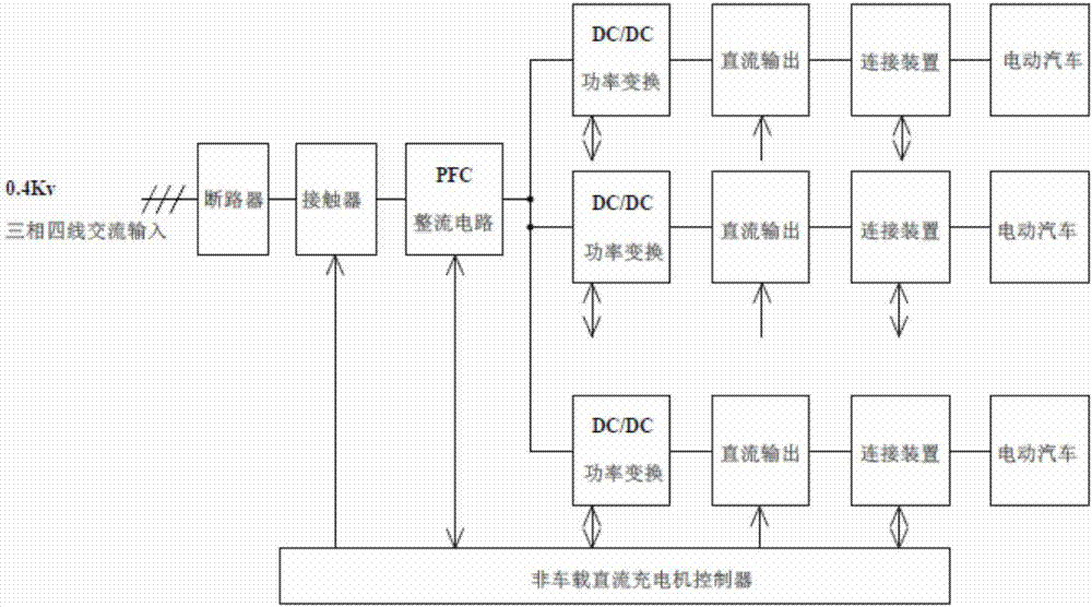
[0028] The structure diagram of the present invention is as Figure 1-5 As shown, the high-power DC charger of the present invention includes a circuit breaker, a contactor, a PFC rectifier circuit, a number of charging circuits, and an off-vehicle DC charger controller, and the three-phase four-wire AC input voltage is connected to the contactor through the circuit breaker , the output of the contactor is connected to the input terminal of the PFC rectifier circuit, the output terminal of the PFC rectifier circuit is divided into multiple channels, which are respectively connected to several charging circuits, and the output terminals of several charging circuits respectively output direct current to the electric vehicle, wherein, the contactor, the PFC rectifier circuit And each charging circuit is connected with the non-vehicle DC charger controller. independently subject to its control.

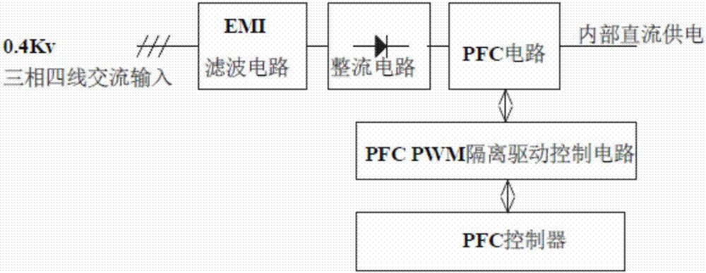
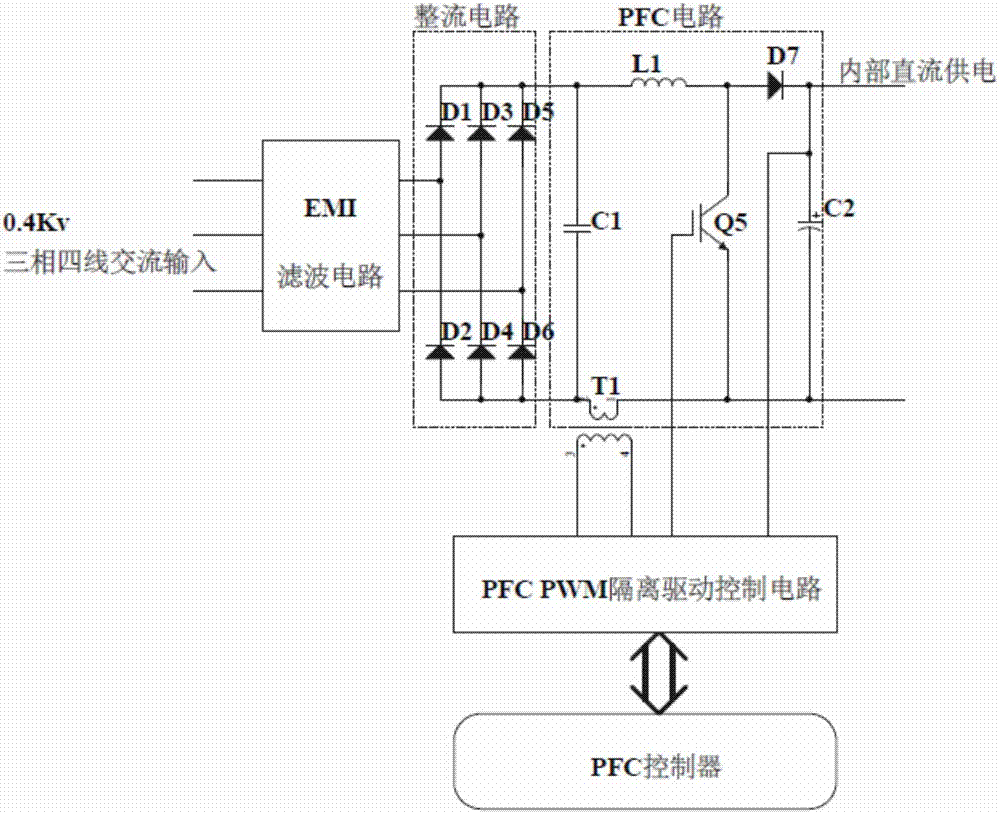
[0029]In this embodiment, the above-mentioned PFC rectifier circuit includes an EMI ...


PUM


Abstract

The present invention relates to a high-power DC charging machine, which comprises a circuit breaker, a contactor, a PFC rectifier circuit, a plurality of charging loops and a non-vehicle-arranged DC charging machine controller. The three-phase four-wire AC input voltage is connected with the contactor through the circuit breaker. The output of the contactor is connected with the input end of the PFC rectifier circuit. The output end of the PFC rectifier circuit is divided into a plurality of branches and the plurality of branches are respectively connected with the plurality of charging loops. The output ends of the plurality of charging loops are used for outputting a direct current to an electric automobile, respectively. The contactor, the PFC rectifier circuit and each charging loop are connected with the non-vehicle-arranged DC charging machine controller and are independently controlled. The high-power DC charging machine is simple in structure, wherein the one-machine and multi-gun design is realized. The utilization rate of the DC charging machine is improved. An insulated gate bipolar transistor (IGBT) or an SIC power module is adopted as a key switch element, so that the reliability of the charging machine is improved. The cost of the charging machine is reduced.

Description

technical field [0001] The invention relates to a high-power DC charger, which relates to the technical field of charging, in particular to the design of a high-power DC charger. Background technique [0002] At present, the domestic DC charger design schemes are all designed under the input condition of AC three-phase four-wire system 380V. The core power conversion component is a three-level topology DC charging module, and the heat dissipation method adopts the module equipped. Active air-cooled heat dissipation + air-cooled or liquid-cooled charger equipped to dissipate heat, its disadvantages are quite obvious: [0003] 1) The operating environment of the DC charger is quite harsh. Generally, the operator does not consider the actual condition of the equipment, and directly installs the equipment in an open-air environment. Such factors seriously damage the service life of the DC charging module and the electronic components and printed circuit boards inside the module...

Claims


Application Information

Patent Timeline
Patent Type & Authority Applications(China)
IPC IPC(8): H02J7/06H02M1/42H02M3/335B60L11/18
CPCB60L53/20B60L2210/10B60L2240/547B60L2240/549H02J7/06H02M1/4225H02M3/3353Y02T10/70Y02T10/7072Y02T10/72Y02T10/92Y02T90/14
Inventor 霍锦强陈刚梁翔飞白海涛何建华邢庆吴志磊陈航左锦王久平
Owner GUANGDONG THOUSANDS OF CITIES & CHARGING STATIONS E VEHICLES OPERATING CO LTD
Why Eureka
Try Eureka