System and method for performing subcarrier decoding on high-frequency signals with subcarrier modulation
A high-frequency signal and sub-carrier technology, applied in the field of decoding, can solve problems such as uncollected data, no explanation or report found, etc., to achieve easy modular production, flexible input frequency bands, and good consistency.
- Summary
- Abstract
- Description
- Claims
- Application Information
AI Technical Summary
Problems solved by technology
Method used
Image
Examples
Embodiment 1
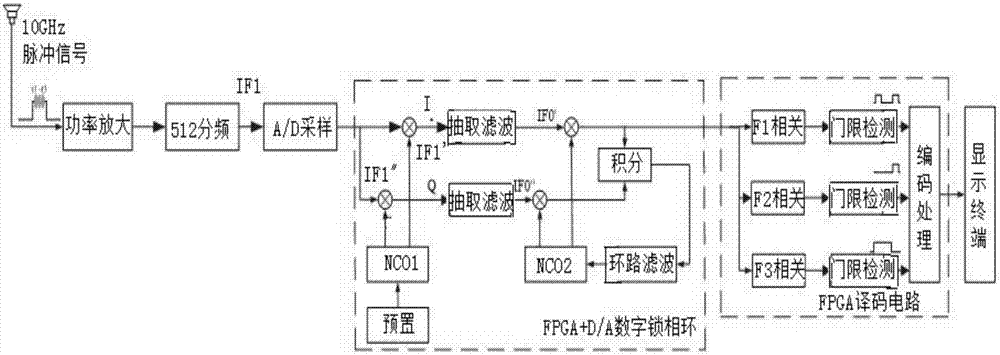
[0057] like figure 1 As shown, the present invention discloses a system for subcarrier decoding of high-frequency signals with subcarrier modulation, including a power adjustment circuit 1, a frequency divider circuit 2, a digital phase-locked loop circuit 4, a digital decoding circuit 5 and Display Terminal 6, where:
[0058] The input end of the power adjustment circuit 1 is connected to the high-frequency signal, and the output end is connected to the frequency divider circuit 2, which is used to amplify or attenuate the power of the high-frequency signal with subcarrier modulation information received at the input end to make it The signal amplitude is controlled within the required power range of the frequency divider circuit 2 for use by the subsequent frequency divider circuit 2; in this embodiment, the specific frequency of the high-frequency signal at the input is not limited, but the frequency division The final signal should fall within the analog signal bandwidth ...
Embodiment 2
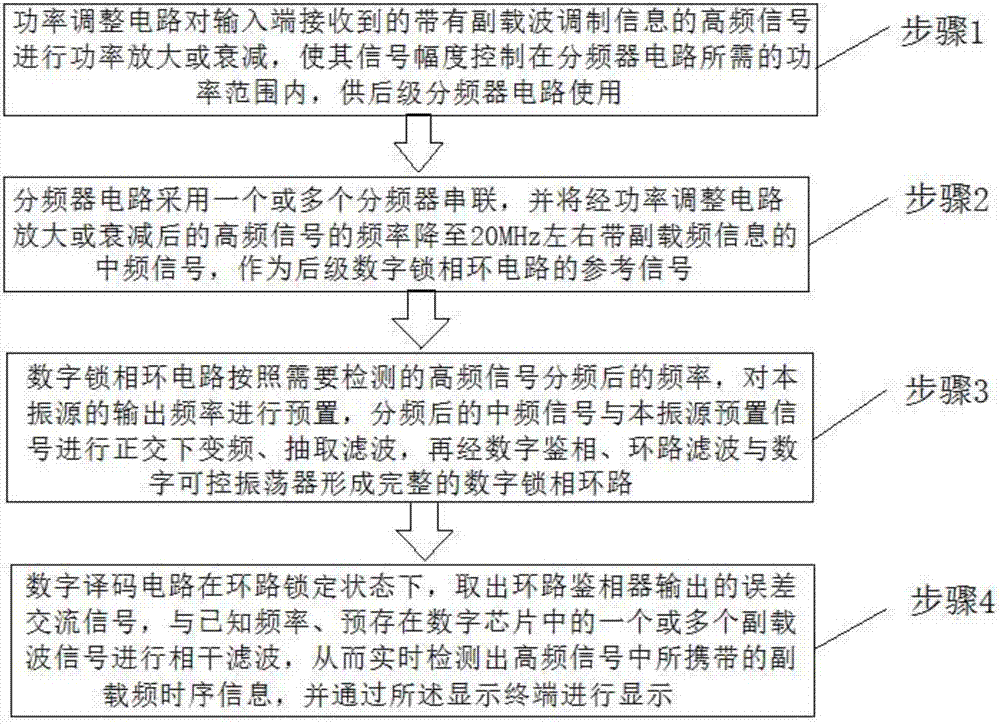
[0071] like figure 2 As shown, the present invention additionally discloses a method for subcarrier decoding of a high frequency signal with subcarrier modulation, comprising the following steps:
[0072] Step 1: The power adjustment circuit 1 amplifies or attenuates the power of the high-frequency signal with subcarrier modulation information received at the input terminal, so that the signal amplitude is controlled within the power range required by the frequency divider circuit 2 for the subsequent stage Frequency divider circuit 2 uses;
[0073] Step 2: The frequency divider circuit 2 adopts one or more frequency dividers in series, and reduces the frequency of the high-frequency signal amplified or attenuated by the power adjustment circuit 1 to an intermediate frequency signal with sub-carrier frequency information of about 20MHz, as a post- The reference signal of the stage digital phase-locked loop circuit 4;
[0074] Step 3: The digital phase-locked loop circuit 4 ...
example
[0081] like image 3As shown, the input signal is a 10GHz radio frequency signal in pulse form received by the horn antenna, including three subcarriers, F1-F3 respectively. Due to the weak signal strength, it is necessary to amplify the power first to meet the input requirements of the frequency division chain, and if necessary, add a corresponding frequency band gating filter to the front end to select the signal. After the radio frequency signal is divided by 512 times, the intermediate frequency signal IF1 of about 20MHz is obtained, and then converted into a digital signal by AD sampling. Preset the frequency of NCO1 (Numerically Controlled Oscillator, digitally controlled oscillator) IF1′ according to the theoretical value of the IF signal. The two IF signals with very close frequencies will need to be The demodulated intermediate frequency signal drops to the vicinity of zero intermediate frequency, that is, two orthogonal IF0', IF0". The zero intermediate frequency si...
PUM
 Abstract
Description
Claims
Application Information
 - R&D
- Intellectual Property
- Life Sciences
- Materials
- Tech Scout
- Unparalleled Data Quality
- Higher Quality Content
- 60% Fewer Hallucinations
Browse by: Latest US Patents, China's latest patents, Technical Efficacy Thesaurus, Application Domain, Technology Topic, Popular Technical Reports.
© 2025 PatSnap. All rights reserved.Legal|Privacy policy|Modern Slavery Act Transparency Statement|Sitemap|About US| Contact US: help@patsnap.com


