Jig backflow mechanism and working method thereof

A technology of jigs and transmission mechanisms, which is applied in the direction of manufacturing tools, structural parts, metal processing equipment, etc., can solve the problems of low production efficiency and high labor intensity, and achieve the effect of high positioning accuracy and fast speed

Inactive Publication Date: 2017-08-08
HUIZHOU CHENGTAI AUTOMATION TECH CO LTD
View PDF4 Cites 13 Cited by
  • Summary
  • Abstract
  • Description
  • Claims
  • Application Information

AI Technical Summary

Problems solved by technology

[0004] At present, in the process of battery assembly, it is necessary to reshape the tabs first and then perform welding and other processes. The traditional method is to manually reshape, and then place the battery cells on the welding machine for welding. The production efficiency is low and the labor intensity is high. , so an automatic device is needed to improve production efficiency

Method used


Image

  • Jig backflow mechanism and working method thereof
  • Jig backflow mechanism and working method thereof
  • Jig backflow mechanism and working method thereof

Examples


Embodiment Construction

[0030] The present invention will be further explained below in conjunction with specific embodiments.

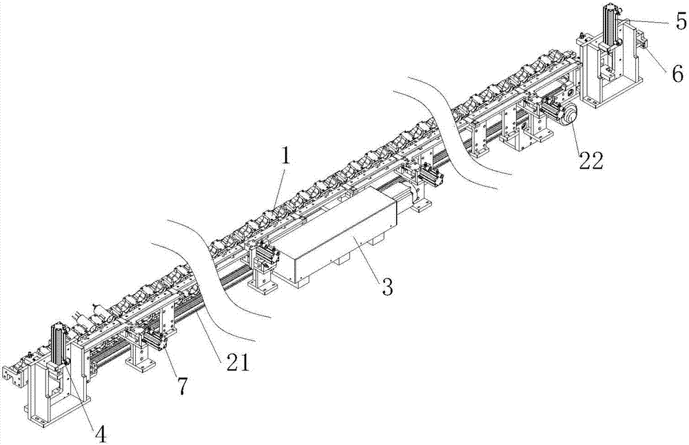
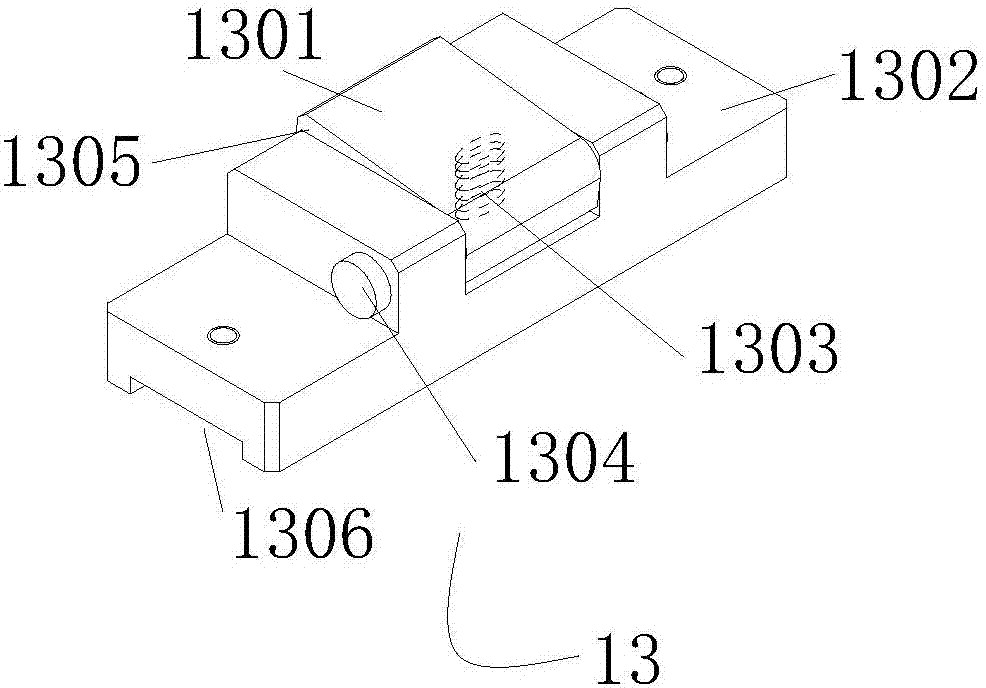
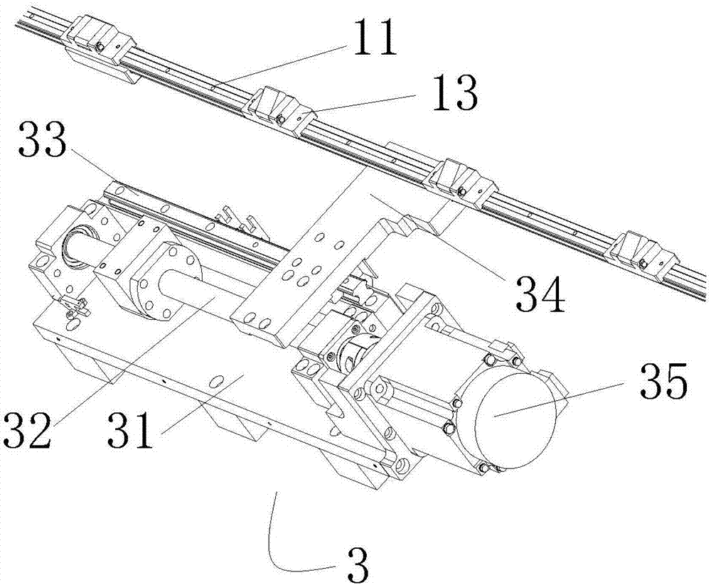
[0031] refer to Figure 1-6 , a jig reflow mechanism, comprising:

[0032] A jig return mechanism, comprising: an upper conveying mechanism 1, a lower conveying mechanism 2, a first elevating mechanism 4, a second elevating mechanism 5 and a pressing mechanism 7, the upper conveying mechanism 1 includes a slide rail 11, and the two sides of the slide rail 11 Two parallel guide rails 12 are symmetrically arranged, and several positioning blocks 13 are arranged equidistantly on the slide rail 11, and a fixture 8 is stuck between two adjacent positioning blocks 13, and the front and rear sides of the fixture 8 are provided with chute and pass through The chute is stuck on the guide rail 12; the servo motor drive mechanism 3 drives the slide rail 11 to move left and right so that the positioning block 13 on the slide rail 11 drives the jig 8 to move left and right on the guide...


PUM


Abstract

The invention discloses a jig backflow mechanism and a working method of the jig backflow mechanism. The jig backflow mechanism comprises an upper-layer conveying mechanism, a lower-layer conveying mechanism, a servo motor driving mechanism, a first lifting mechanism, a second lifting mechanism and a compaction mechanism. Jigs can move in circles between the upper-layer conveying mechanism and the lower-layer conveying mechanism, the upper-layer conveying mechanism conveys the jigs to working stations, and the jigs are returned from the discharge side to the feeding side through the lower-layer conveying mechanism. The jigs are driven by a servo motor and a ball screw mechanism to be transferred, and the jig backflow mechanism has the advantages of being high in positioning precision and high in speed. The jig backflow mechanism achieves jig backflow transfer through the two lifting mechanisms, and has the characteristics of being high in efficiency and high in precision. The whole system achieves jig backflow through a belt assembly line mechanism.

Description

technical field [0001] The invention relates to the technical field of battery tab production, in particular to a jig reflow mechanism and a working method thereof. Background technique [0002] Tabs are a raw material for lithium-ion polymer battery products. For example, mobile phone batteries, bluetooth batteries, and notebook batteries used in our daily life all need to use tabs. The battery is divided into positive and negative poles, and the tabs are the metal conductors that lead the positive and negative poles out of the battery. In layman's terms, the ears of the positive and negative poles of the battery are the contact points when charging and discharging. [0003] At present, the welding machines for battery tabs and tabs mainly include resistance welding and ultrasonic metal welding. Resistance welding is to use the resistance heat and a large amount of plastic deformation energy of the metal itself in the welding zone to make the metal atoms on the two separa...

Claims


Application Information

Patent Timeline
Patent Type & Authority Applications(China)
IPC IPC(8): B23K37/00H01M2/26H01M50/531
CPCB23K37/00H01M50/531Y02E60/10
Inventor 黄向东何茂水
Owner HUIZHOU CHENGTAI AUTOMATION TECH CO LTD
Why Eureka
Try Eureka