
Bar continuous-type automatic machining equipment

A technology for processing equipment and bar materials, which is applied in the field of continuous automatic processing equipment for bar materials, can solve the problems of manpower consumption, low degree of automation and low production efficiency, and achieve the effects of improved efficiency, high work efficiency and convenient positioning.

Inactive Publication Date: 2017-08-08
湖州多玛智能科技股份有限公司
View PDF1 Cites 3 Cited by
  • Summary
  • Abstract
  • Description
  • Claims
  • Application Information

AI Technical Summary

Problems solved by technology

[0005] The purpose of the present invention is to address the deficiencies of the prior art, by setting a feeding mechanism before the rolling turning mechanism and setting a positioning support mechanism and a horizontal output mechanism that can quickly transport the sawed bar to the feeding mechanism at the front end of the feeding mechanism In turn, it overcomes the problems of low automation, low production efficiency and labor-consuming problems in the process of bar material transmission and processing

Method used


Image

  • Bar continuous-type automatic machining equipment
  • Bar continuous-type automatic machining equipment
  • Bar continuous-type automatic machining equipment

Examples


Embodiment 1

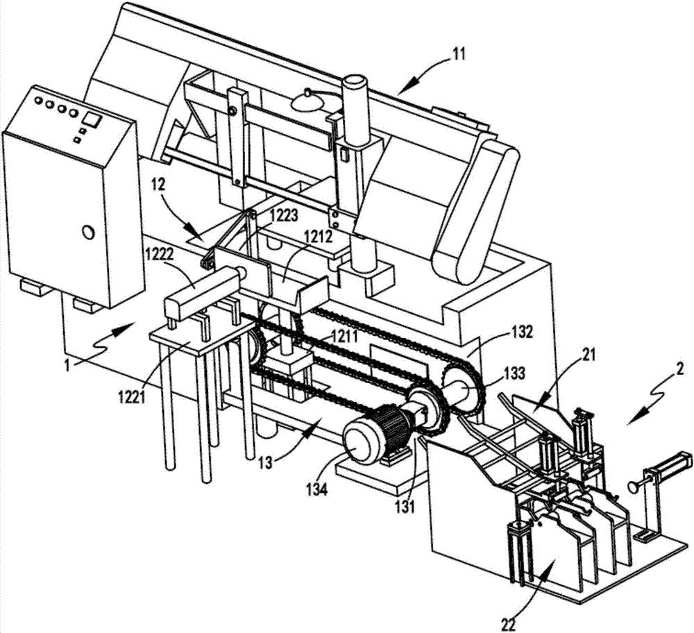
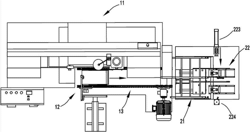
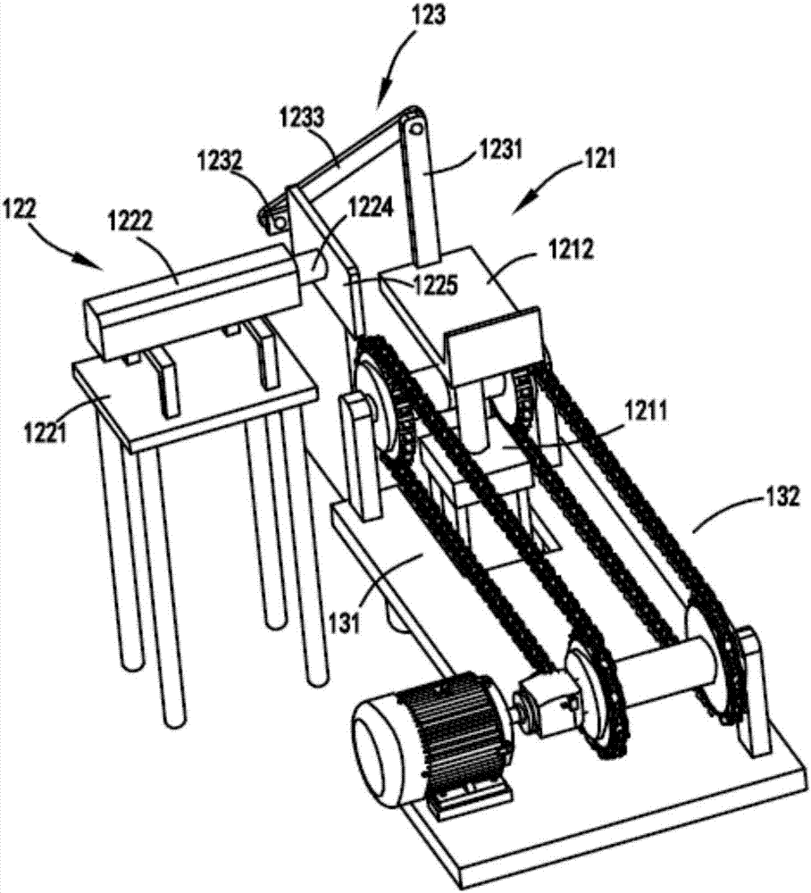
[0045] figure 1 It is a schematic diagram of the continuous automatic processing equipment for bars, figure 2 It is a top view schematic diagram of bar continuous automatic processing equipment, image 3 It is a structural schematic diagram of the positioning support mechanism and the horizontal output mechanism, Figure 4 is the structural schematic diagram of the turning part, Figure 5 It is a schematic diagram of the structure of the feeding mechanism, Image 6 It is a schematic side view of the bar when it is on the conveying device a and conveying device b, Figure 7 It is a schematic diagram of the structure of the push device, Figure 8 It is a schematic diagram of the structure when the lifting and supporting device drives the bar to move to the placement groove and the inclined surface respectively, Figure 9 Schematic diagram of the structure when the lifting and supporting device moves upward to accept the bar on the buffer rack, Figure 10 Schematic diagram...

Embodiment 2

[0067] Such as figure 1 , figure 2 , image 3 , Figure 4 , Figure 5 , Image 6 , Figure 7 , Figure 8 , Figure 9 with Figure 10 As shown, the components that are the same as or corresponding to those in the first embodiment are marked with the corresponding reference numerals in the first embodiment. For the sake of simplicity, only the differences from the first embodiment will be described below. The difference between the second embodiment and the first embodiment is that the positioning support mechanism 12 includes a lifting transfer device 121, a positioning device 122 arranged on one side of the lifting transfer device 121, and a positioning device 122 arranged between the lifting transfer device 121 and the positioning device 122. There is a transmission device 123 between them, and the transmission device 123 drives the positioning device 122 to move in the horizontal direction during the process of the lifting transfer device 121 moving in the vertical ...


PUM


Abstract

The invention relates to a bar material continuous automatic processing equipment, comprising a feeding part, the feeding part includes a sawing mechanism for cutting the bar material according to a certain length, and is used for positioning the bar material before sawing and The positioning support mechanism that drives the sawed bar to move down in the vertical direction and the horizontal output mechanism that is arranged below the positioning support mechanism to accept the bar on the positioning support mechanism and drive the bar to output backward in the horizontal direction; turning Part, the turning part is set at the rear end of the feeding part, the turning part is used to accept the bar delivered by the feeding part, and transfer the bar to be turned to the turning station while completing the turning on the turning station The feeding mechanism for the processed bar material to be output backward and the rolling turning mechanism for positioning and turning the bar material on the turning station; the invention overcomes the low degree of automation, low production efficiency and expensive manpower problem.

Description

technical field [0001] The invention relates to the technical field of sawing machine equipment, in particular to a bar material continuous automatic processing equipment. Background technique [0002] A Chinese invention patent with the application publication number CN105057786A discloses a band sawing machine. The device is equipped with a pulley in the saw frame, and the band saw blade is wound around the pulley. A pressure sensor is set at the contact point between the pulley and the band saw blade. And a clamping device connected with the cylinder driving device is arranged on the workpiece placing table; thus, the band saw blade can be installed conveniently and quickly, and the band saw blade will not be damaged during the installation process. But it has the following problems: [0003] 1. The equipment does not have the function of quickly positioning the bar and outputting the sawed bar quickly and automatically. [0004] 2. The equipment does not have the funct...

Claims


Application Information

Patent Timeline
Patent Type & Authority Applications(China)
IPC IPC(8): B23P23/06
CPCB23P23/06
Inventor 章金金
Owner 湖州多玛智能科技股份有限公司
Learn More