Energy adjusting system
A technology of energy adjustment and inertial body, which is applied in the direction of fluid transmission, belt/chain/gear, mechanical equipment, etc., can solve the problem of affecting system noise, vibration life and efficiency, unfavorable prime mover power shaft torque distribution, and affecting system pollution emissions and other problems, to achieve the effect of simple structure, good environmental performance and good load response
- Summary
- Abstract
- Description
- Claims
- Application Information
AI Technical Summary
Problems solved by technology
Method used
Image
Examples
Embodiment 1
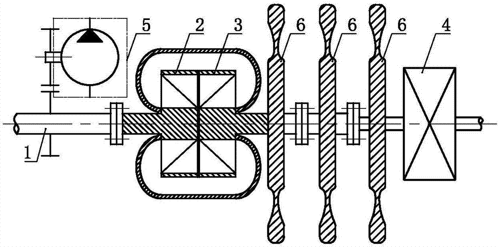
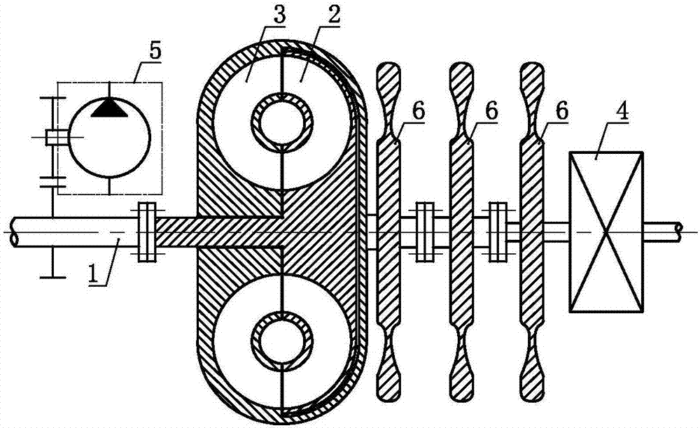
[0041] An energy regulation system such as Figure 1.1 and 1.2 As shown, it includes a power shaft 1, an impeller A 2, an impeller B 3, a transmission 4 and a hydraulic pump 5, the impeller A 2 and the impeller B 3 are connected in series, and the power shaft 1 and the impeller A 2 are transmitted Setting, the power shaft 1 is set in transmission with the hydraulic pump 5, the impeller B3 is set in transmission with the transmission 4, on the impeller B3, between the impeller B3 and the transmission 4 Inertia bodies 6 are arranged on the transmission parts of the transmission and on the transmission parts of the transmission 4 .
[0042] As a changeable implementation mode, in Embodiment 1 of the present invention, one or both of the transmission member between the impeller B 3 , the impeller B 3 and the transmission 4 and the transmission 4 can also be selectively selected. Inertia body 6 is set on each.
Embodiment 2
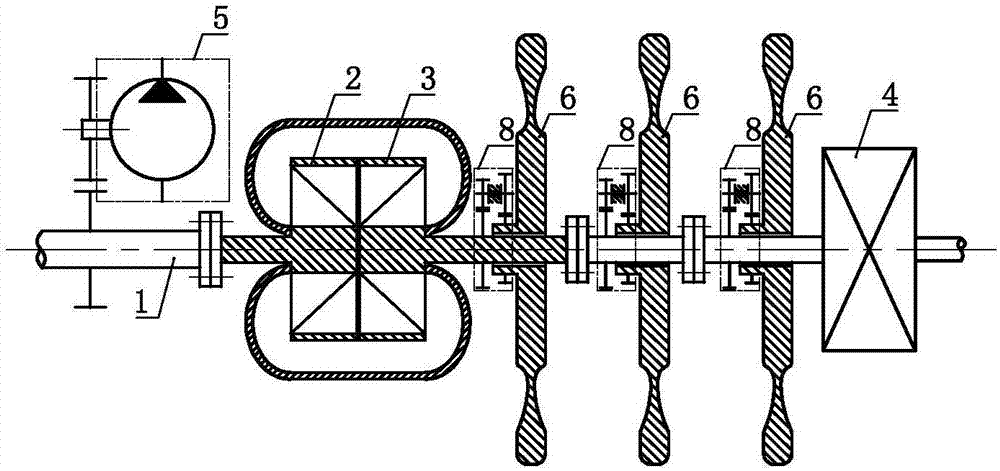
[0044] An energy regulation system such as figure 2 As shown, it includes a power shaft 1, an impeller A 2, an impeller B 3, a transmission 4 and a hydraulic pump 5, the impeller A 2 and the impeller B 3 are connected in series, and the power shaft 1 and the impeller A 2 are transmitted Setting, the power shaft 1 is set in transmission with the hydraulic pump 5, the impeller B 3 is set in transmission with the transmission 4, the transmission member between the impeller B 3, the impeller B 3 and the transmission 4 And the transmission part of the transmission 4 is set through the transmission of the speed increasing mechanism 8 and the inertia body 6 .
[0045] As a changeable implementation mode, in Embodiment 2 of the present invention, the impeller B 3 , the transmission member between the impeller B 3 and the transmission 4, and the transmission member of the transmission 4 can also be selected selectively. One or two pieces are set through speed-increasing mechanism 8 a...
Embodiment 3
[0048] An energy regulation system such as Figure 3.1 and 3.2 As shown, including power shaft 1, impeller A 2, impeller B 3, impeller AB7, transmission 4 and hydraulic pump 5, the impeller A 2, the impeller B 3 and the impeller AB 7 are connected in series, and the power The shaft 1 is set in transmission with the impeller A 2, the power shaft 1 is set in transmission with the hydraulic pump 5, the impeller B 3 is set in transmission with the transmission 4, and between the impeller B 3 and the transmission 4 Inertia bodies 6 are arranged on the transmission parts between and on the transmission parts of the transmission 4 .
[0049] As a changeable embodiment, Embodiment 3 of the present invention can also selectively choose to make the impeller B 3 , the transmission member between the impeller B 3 and the transmission 4 and the transmission member of the transmission 4 Inertia body 6 is set on one or two or three.
PUM
 Abstract
Description
Claims
Application Information
 - R&D
- Intellectual Property
- Life Sciences
- Materials
- Tech Scout
- Unparalleled Data Quality
- Higher Quality Content
- 60% Fewer Hallucinations
Browse by: Latest US Patents, China's latest patents, Technical Efficacy Thesaurus, Application Domain, Technology Topic, Popular Technical Reports.
© 2025 PatSnap. All rights reserved.Legal|Privacy policy|Modern Slavery Act Transparency Statement|Sitemap|About US| Contact US: help@patsnap.com


