Converter cabinet

A converter and cabinet technology, which is applied in the direction of converting AC power input to DC power output, converting equipment structural parts, electrical equipment structural parts, etc., can solve the problems of high manual assembly costs, inconvenient capacity expansion, and converter Cabinets are inconvenient to assemble and connect, so as to alleviate heat dissipation problems, facilitate capacity expansion, and eliminate the trouble of cross-cabinet connection of busbars

Pending Publication Date: 2017-08-08
SHENZHEN HOPEWIND ELECTRIC CO LTD
View PDF7 Cites 7 Cited by
  • Summary
  • Abstract
  • Description
  • Claims
  • Application Information

AI Technical Summary

Problems solved by technology

[0003] The technical purpose of the present invention is to overcome the technical problems that the structure of the converter cabinet in the prior art is not convenient for assembly and wiring, the cost of manual assembly is high, and it is inconvenient to expand the capacity; Converter cabinet for easy capacity expansion

Method used


Image

  • Converter cabinet
  • Converter cabinet
  • Converter cabinet

Examples


Embodiment Construction

[0027] Embodiments of the present invention are described in detail below, examples of which are shown in the drawings, wherein the same or similar reference numerals designate the same or similar elements or elements having the same or similar functions throughout. The embodiments described below by referring to the figures are exemplary only for explaining the present invention and should not be construed as limiting the present invention.

[0028] In describing the present invention, it should be understood that the terms "center", "longitudinal", "transverse", "upper", "lower", "front", "rear", "left", "right", " The orientations or positional relationships indicated by "vertical", "horizontal", "top", "bottom", "inner" and "outer" are based on the orientations or positional relationships shown in the drawings, and are only for the convenience of describing the present invention and Simplified descriptions, rather than indicating or implying that the device or element refe...


PUM


Abstract

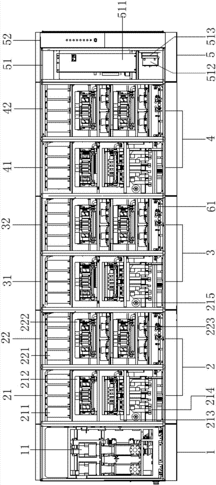
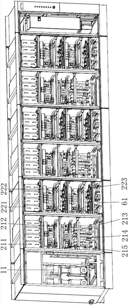
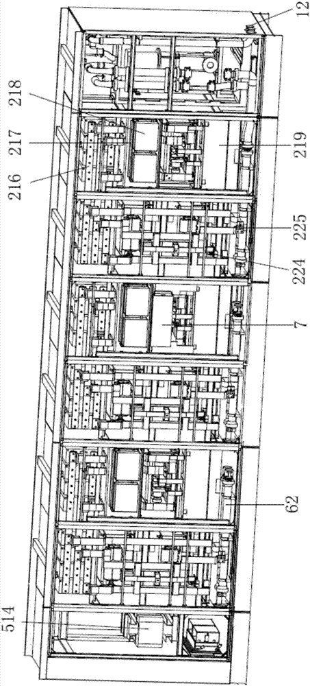
A converter cabinet disclosed by the present invention at least comprises three sub-cabinets, each sub-cabinet comprises a cabinet body, and a first DC bus capacitor module, a rectifier power module, a second DC bus capacitor module and an inverter power module are at least arranged inside the cabinet body. The first and second DC bus capacitor modules are arranged horizontally and parallelly and are electrically connected via a conductor, the rectifier power module is located at the lower part of the first DC bus capacitor module, and a lower incoming line of the rectifier power module is connected with the first DC bus capacitor module via a conductor. The inverter power module is located at the lower part of the second DC bus capacitor module, a lower incoming line of the inverter power module is connected with the second DC bus capacitor module via a conductor, and the structures of the sub-cabinets are same and independent to form one phase.

Description

technical field [0001] The present invention relates to a cabinet, more specifically, to a converter cabinet. Background technique [0002] The medium-voltage high-power converter cabinets in the prior art are generally divided into rectifier cabinets, inverter cabinets and DC filtering parts, of which: 1. The rectifier cabinet is used to convert AC power into DC power; 2. The inverter The cabinet group is used to convert DC power into AC power; 3. The DC filter part is used to filter the rectified DC power, so as to obtain relatively smooth DC power and improve the quality of power supply. The DC filtering part is generally used as an independent cabinet group. The rectifier cabinet group and the inverter cabinet group respectively include three-phase main power parts, and the three cabinet groups are connected through DC busbars; It is not convenient to assemble and connect the two DC busbars. And for capacity expansion, cabinet groups can only be arranged in parallel, w...

Claims


Application Information

Patent Timeline
Patent Type & Authority Applications(China)
IPC IPC(8): H02M1/00H02M7/00H05K7/20
CPCH02M1/00H02M7/003H05K7/20927
Inventor 王子健张小蒙王武华李海龙周党生
Owner SHENZHEN HOPEWIND ELECTRIC CO LTD
Why Eureka
Try Eureka