Electromagnetic heating apparatus and heat control circuit and low-power heat control method thereof

A technology of electromagnetic heating device and heating control circuit, which is applied in electric heating device, induction heating control, electric/magnetic/electromagnetic heating and other directions, can solve the problems of high transient current peak value of IGBT, IGBT burning, IGBT heating, etc., and achieve the turn-on current The effect of reducing, reducing turn-on noise, and reducing damage

Active Publication Date: 2017-08-08
FOSHAN SHUNDE MIDEA ELECTRICAL HEATING APPLIANCES MFG CO LTD
View PDF11 Cites 13 Cited by
  • Summary
  • Abstract
  • Description
  • Claims
  • Application Information

AI Technical Summary

Problems solved by technology

[0003] (1) The IGBT voltage is turned on ahead of time, and the moment of turning on will cause the peak value of the IGBT transient current to be high, which will easily exceed the IGBT current peak value specification limit and damage the IGBT;
[0004] (2) The IGBT will generate serious heat, and it is necessary to strengthen the heat dissipation of the IGBT (such as increasing the heat sink, increasing the fan speed, etc.) to meet the temperature rise requirements of the IGBT;
[0005] (3) If low power is achieved in the duty cycle heating method, that is, the intermittent heating method is adopted, due to the existence of the filter capacitor, there will be a hard turn-on phenomenon when the IGBT is turned on in the next cycle, which will easily cause the IGBT to burn out

Method used


Image

  • Electromagnetic heating apparatus and heat control circuit and low-power heat control method thereof
  • Electromagnetic heating apparatus and heat control circuit and low-power heat control method thereof
  • Electromagnetic heating apparatus and heat control circuit and low-power heat control method thereof

Examples


Embodiment Construction

[0034] Embodiments of the present invention are described in detail below, examples of which are shown in the drawings, wherein the same or similar reference numerals designate the same or similar elements or elements having the same or similar functions throughout. The embodiments described below by referring to the figures are exemplary and are intended to explain the present invention and should not be construed as limiting the present invention.

[0035] The following describes the heating control circuit of the electromagnetic heating device, the low-power heating control method of the electromagnetic heating device and the electromagnetic heating device according to the embodiments of the present invention with reference to the accompanying drawings.

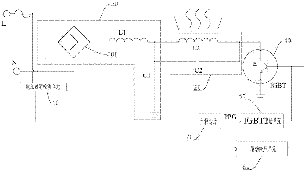
[0036] figure 1 It is a schematic block diagram of a heating control circuit of an electromagnetic heating device according to an embodiment of the present invention. Such as figure 1 As shown, the heating control circui...


PUM


Abstract

The invention discloses an electromagnetic heating apparatus and a heat control circuit and a low-power heat control method thereof. The heat control circuit comprises a voltage zero-crossing detection unit, a resonance heating unit, a rectifying and filtering unit, a power switch tube, a driving unit, a driving voltage transformation unit and a main control unit, wherein the voltage zero-crossing detection unit is used for detecting a voltage zero-crossing signal of an alternating current power supply; the driving unit is connected with the driving end of the power switch tube to drive the switch-on and switch-off of the power switch tube; the driving voltage transformation unit is connected with the driving end of the power switch tube to change the driving voltage of the power switch tube; the main control unit controls the power switch tube to work under drive of a first driving voltage according to the voltage zero-crossing signal before the zero-crossing point of the alternating current power supply through judgment, and controls the power switch tube to work under drive of a second driving voltage when the collector voltage of the power switch tube oscillates to be the minimum, so as to start the power switch tube in a voltage transformation manner, in order to lower the risk of damage of the power switch tube and lower switch-on noise.

Description

technical field [0001] The invention relates to the technical field of electromagnetic heating, in particular to a heating control circuit of an electromagnetic heating device, a low-power heating control method of an electromagnetic heating device and an electromagnetic heating device. Background technique [0002] At present, the electromagnetic resonance circuit of a single IGBT (Insulated Gate Bipolar Transistor, Insulated Gate Bipolar Transistor) usually adopts a parallel resonance method, and when using the resonance parameters to realize the high-power operation of the induction cooker, if it operates in the continuous low-power segment, it will The following problem occurs: [0003] (1) The IGBT voltage is turned on ahead of time, and the moment of turning on will cause the peak value of the IGBT transient current to be high, which will easily exceed the IGBT current peak value specification limit and damage the IGBT; [0004] (2) The IGBT will generate serious heat...

Claims


Application Information

Patent Timeline
Patent Type & Authority Applications(China)
IPC IPC(8): H05B6/06
CPCH05B6/062H05B2206/02
Inventor 江德勇王云峰曾露添
Owner FOSHAN SHUNDE MIDEA ELECTRICAL HEATING APPLIANCES MFG CO LTD
Why Eureka
Try Eureka