Cement mixing equipment for construction

A technology for mixing equipment and construction, used in cement mixing devices, clay preparation devices, liquid batching supply devices, etc., can solve the problems of waste of resources, increase costs, slow mixing speed of mixing shafts, etc., to reduce waste of resources, prevent Residual solidification, the effect of preventing cement solidification

Inactive Publication Date: 2017-08-11
六安市我罗生工业设计有限公司
View PDF0 Cites 9 Cited by
  • Summary
  • Abstract
  • Description
  • Claims
  • Application Information

AI Technical Summary

Problems solved by technology

When the current mixer is pouring cement, it will generate a lot of dust, which not only pollutes the environment, but also affects people's health.
Although some current mixers are also equipped with dust removal devices, the dust removal effect is poor, and the waste of resources is serious, which increases the cost of use
Moreover, the current mixers all use a single mixing blade to cooperate with multiple mixing blades for mixing. The stirring speed of the stirring shaft of this structure is slow and the mixing range in contact with the cement slurry is limited, so it cannot be effectively stirred evenly. It is possible to solidify in the cylinder, which causes inconvenience to use; therefore it is necessary to improve

Method used


Image

  • Cement mixing equipment for construction
  • Cement mixing equipment for construction
  • Cement mixing equipment for construction

Examples


Embodiment Construction

[0017] The following will clearly and completely describe the technical solutions in the embodiments of the present invention with reference to the accompanying drawings in the embodiments of the present invention. Obviously, the described embodiments are only some, not all, embodiments of the present invention. Based on the embodiments of the present invention, all other embodiments obtained by persons of ordinary skill in the art without making creative efforts belong to the protection scope of the present invention.

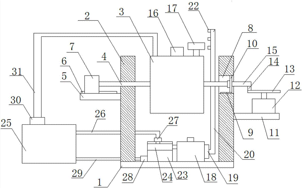
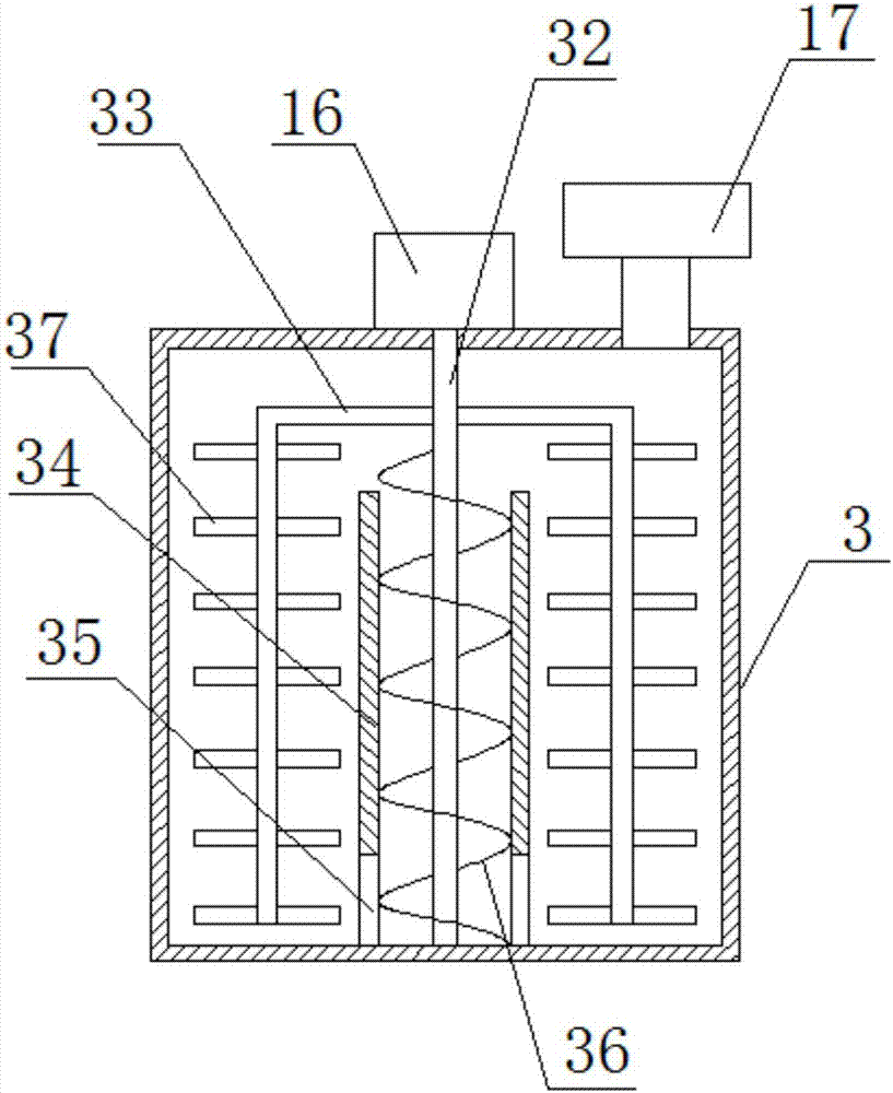
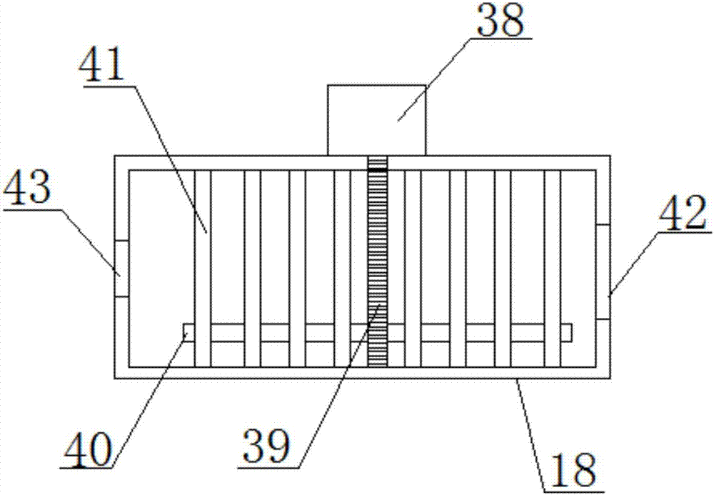
[0018] see Figure 1~4 , in the embodiment of the present invention, a cement mixing equipment for construction, comprising a base 1, a mixing tank 3, and a reservoir 25, the underside of the base 1 is provided with a shock-absorbing pad, and the upper side of the base 1 is left-right symmetrical The supporting plate 2 is provided, the left and right sides of the mixing box 3 are provided with a rotating shaft 4, the left side of the left supporting plate 2 is...


PUM


Abstract

The invention discloses a cement mixing equipment for construction, which comprises a base, a mixing box, and a water storage tank. Support plates are symmetrically arranged on the upper side of the base, and rotating shafts are arranged on the left and right sides of the mixing box. The left side is provided with a mounting plate, the upper side of the mounting plate is provided with a first slide rail, the upper side of the first slide rail is provided with a first motor, the right side of the right support plate is provided with a bracket, and the upper side of the bracket is provided with a The second motor, the output end of the second motor is provided with a turntable, the upper periphery of the turntable is provided with a rotating rod, the upper end of the rotating rod is provided with a connecting rod, the upper part of the support plate on the right side is provided with a cavity, and the inside of the cavity is provided with The second slide rail, the second slide rail is provided with a connecting plate, the right side of the connecting plate is provided with a connecting rod, the right end of the connecting rod is rotatably connected with the rotating rod, and the upper side of the base is provided with a first dust removal box and a second dust removal box . The invention has the advantages of simple structure, convenient use, good stirring effect, strong dust removal effect and high resource utilization rate.

Description

technical field [0001] The invention relates to the technical field of construction machinery, in particular to cement mixing equipment for construction. Background technique [0002] With the rapid economic development in recent years, the civil construction industry is getting hotter and hotter, and the demand for cement is increasing. Mixers are widely used in chemical, construction, food, environmental protection and other industrial production. From the perspective of their operation , Stirring can promote two or more materials to disperse and fully contact each other, and then achieve uniform density field, concentration field, and temperature field; cement mixer is an important part of the construction industry, and the materials enter the equipment through the feed port , The stirring device rotates and stirs at high speed, so that the materials are rolled and mixed rapidly in an all-round continuous cycle, and finally the materials are discharged through the dischar...

Claims


Application Information

Patent Timeline
Patent Type & Authority Applications(China)
IPC IPC(8): B28C5/16B28C5/08B28C7/12B01D50/00
CPCB28C5/16B01D50/00B28C5/0806B28C7/126
Inventor 孙益博刘锁
Owner 六安市我罗生工业设计有限公司
Why Eureka
Try Eureka