Supercharge Your Innovation With Domain-Expert AI Agents!

Energy-saving and high-efficiency hydraulic press

A press and hydraulic technology, applied in the field of hydraulic presses, can solve the problems of low efficiency, unfavorable press layout, large volume of high-power motors, etc.

Active Publication Date: 2018-11-23
浙江柱达机械科技有限公司
View PDF6 Cites 0 Cited by
  • Summary
  • Abstract
  • Description
  • Claims
  • Application Information

AI Technical Summary

Problems solved by technology

[0002] Hydraulic presses, also known as hydroforming presses, are used for the forming and processing of various metal materials and non-metallic materials. The traditional hydraulic presses use the motor to directly drive the oil pump, and then the oil pump drives the piston on the oil cylinder to move upwards, thereby It is used to press out the required parts. When the pressure value of the pressing parts is relatively large, a high-power motor is required to generate enough torque to drive the oil pump, thereby driving the oil cylinder to move upward. The high-power motor is not only relatively large in size, but also consumes high energy consumption. The high price is not only unfavorable to the layout of the press space, but also low in efficiency (the oil cylinder needs to be supplied with oil, and the piston can rise, the greater the pressure of the hydraulic oil output by the oil pump, the less the output oil, in order to ensure the high pressure of the hydraulic oil, similar in the working principle of automobile gearbox)

Method used


Image

  • Energy-saving and high-efficiency hydraulic press
  • Energy-saving and high-efficiency hydraulic press
  • Energy-saving and high-efficiency hydraulic press

Examples


Embodiment Construction

[0029] The present invention will be further described below in conjunction with accompanying drawing:

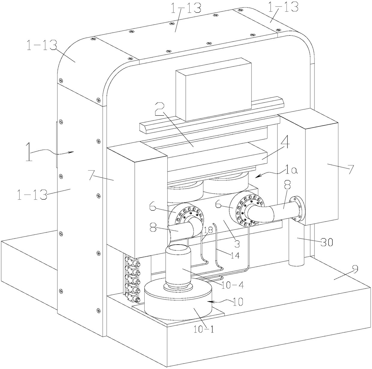
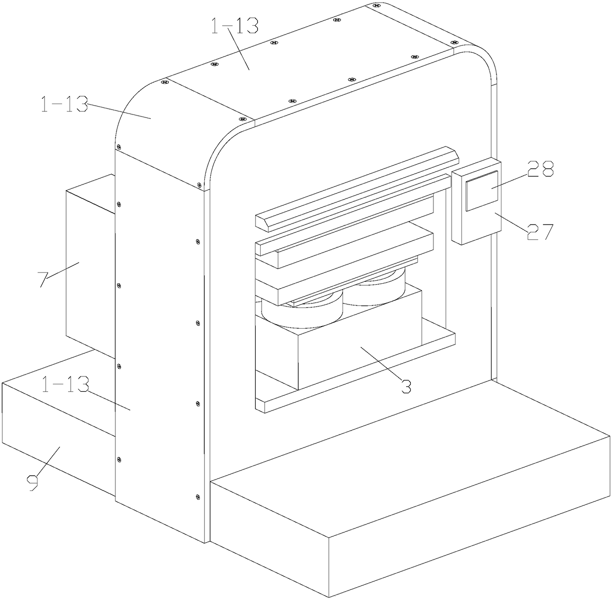
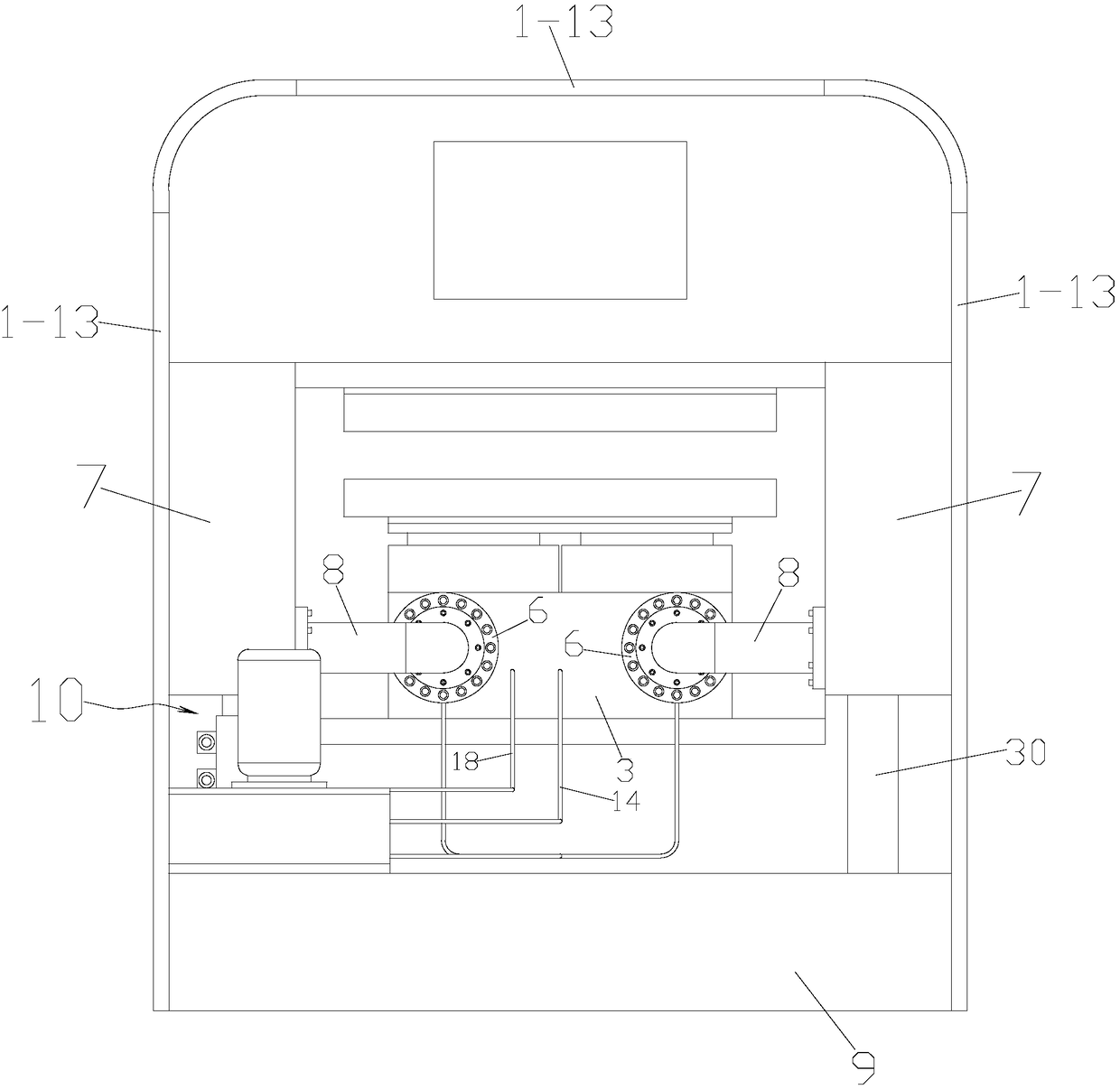
[0030] Referring to the accompanying drawings: This energy-saving and high-efficiency hydraulic press includes a frame 1, which is provided with a cylinder workbench 1a, a stopper 2 is fixed on the top surface of the cylinder workbench 1a, and a pressure cylinder is fixed on the cylinder workbench 1a. Oil cylinder 3, pressure block 4 is fixed on the piston of pressure oil cylinder 3, oil cylinder table 1a is provided with lifting oil cylinder 5 that drives pressure block 4 to rise, and the cylinder body of pressure oil cylinder 3 is fixed with pressure oil cylinder 3. Liquid valve 6, oil storage tank 7 is fixed on frame 1, connecting pipe 8 is connected between the bottom of oil storage tank 7 and filling valve 6, oil tank 9 is fixed on the side of frame 1, power assembly 10 is fixed on oil tank 9 , the power assembly 10 includes a flywheel seat 10-1 and a flywheel 10-2 ins...


PUM


Abstract

The invention discloses an energy-saving efficient hydraulic press. The energy-saving efficient hydraulic press comprises a rack and an oil cylinder workbench, wherein a baffle block is fixedly arranged on the oil cylinder workbench; a pressure oil cylinder is fixedly arranged on the oil cylinder workbench; a pressure block is fixedly arranged on the pressure oil cylinder; an ascending oil cylinder is arranged on the oil cylinder workbench; a liquid filling valve is fixedly arranged on the cylinder body of the pressure oil cylinder; an oil storage tank is fixedly arranged on the rack; a connecting tube is in communication between the bottom of the oil storage tank and the liquid filling valve; an oil tank is fixedly arranged on the rack; a power assembly is fixedly arranged on the oil tank; a solenoid reversing valve I and a superposed type hydraulic-control one-way valve I are arranged between the ascending oil cylinder and a pump I of a duplex pump; a solenoid reversing valve II and a superposed type hydraulic-control one-way valve II are arranged between the pressure oil cylinder and a pump II of the duplex pump; a solenoid reversing valve III is arranged on the side part of the liquid filling valve; a pipeline is connected between each solenoid reversing valve and each superposed type hydraulic-control one-way valve; and a solenoid reversing valve III, a solenoid reversing valve IV, a solenoid reversing valve IV, a superposed type overflow valve I and a superposed type overflow valve II are arranged on the side parts of the pipelines. The energy-saving efficient hydraulic press is energy-saving and is worthy of being popularized and applied.

Description

technical field [0001] The invention relates to the field of hydraulic machinery, in particular to a hydraulic press for leather embossing. Background technique [0002] Hydraulic presses, also known as hydroforming presses, are used for the forming and processing of various metal materials and non-metallic materials. The traditional hydraulic presses use the motor to directly drive the oil pump, and then the oil pump drives the piston on the oil cylinder to move upwards, thereby It is used to press out the required parts. When the pressure value of the pressing parts is relatively large, a high-power motor is required to generate enough torque to drive the oil pump, thereby driving the oil cylinder to move upward. The high-power motor is not only relatively large in size, but also consumes high energy consumption. The high price is not only unfavorable to the layout of the press space, but also low in efficiency (the oil cylinder needs to be supplied with oil, and the pisto...

Claims


Application Information

Patent Timeline
Patent Type & Authority Patents(China)
IPC IPC(8): B30B1/32B30B15/18
CPCB30B1/32B30B15/18
Inventor 蔡军辉蔡砥柱
Owner 浙江柱达机械科技有限公司
Features
  • R&D
  • Intellectual Property
  • Life Sciences
  • Materials
  • Tech Scout
  • Unparalleled Data Quality
  • Higher Quality Content
  • 60% Fewer Hallucinations
Learn More