Sludge energy modification system

A technology for energy and sludge, which is applied in the fields of sludge detoxification, sludge treatment, water/sludge/sewage treatment, etc., to facilitate large-scale popularization and use, eliminate heavy metal pollution, and promote combustion.

Active Publication Date: 2017-08-11
长沙紫宸科技开发有限公司
View PDF3 Cites 0 Cited by
  • Summary
  • Abstract
  • Description
  • Claims
  • Application Information

AI Technical Summary

Problems solved by technology

[0005] The technical problem to be solved by the present invention is to provide a method that can quickly and effectively sterilize, modify, and quickly dehydrate sludge into mixed fuel for the problems of sludge energy conversion, reduction, and secondary environmental pollution, which is beneficial to sewage. Sludge energy conversion and resource utilization, and no secondary pollution sludge energy modification system

Method used


Image

  • Sludge energy modification system
  • Sludge energy modification system

Examples


Embodiment 1

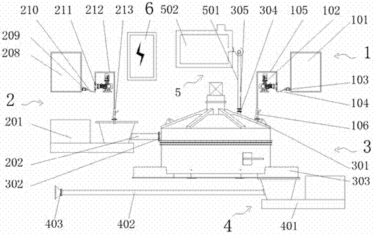
[0029] refer to figure 1 , the present embodiment includes a modifier adding distributing device 1, a sludge feeding device 2, a sludge modified mixing device 3, a modified sludge distributing device 4, a poly-exhaust gas treatment device 5 and an electric control device 6; the sludge The mud modification and mixing device 3 is provided with a modifier feeding port 301, a sludge feeding port 302, a discharge port 303, and a gas gathering port 304, and the gas collecting port 304 is connected to the gas collecting port 305 through the gas collecting and exhausting pipeline valve 305. The gas treatment device 5 is connected, the modifier feeding device 1 is connected to the modifier feeding port 301, the sludge feeding device 2 is connected to the sludge feeding port 302, and the modified sludge feeding device 4 is connected to the discharge port The feed port 303 is connected, and the electric control device 6 is respectively connected to the modifier adding distributing device...

Embodiment 2

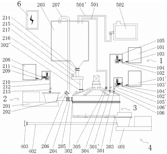
[0041] refer to figure 2 , the difference between this embodiment and embodiment 1 is:

[0042] (1) There is a second modifier adding distributing device, the second modifier adding distributing device includes a second modifier tank 101', a second modifier meter feed pump 102', a second modifier Agent pipeline valve 103', second modifier pipeline I 104', second modifier pipeline II 105' and second modifier adding distributor 106', the second modifier tank 101' is connected to the second modifier The agent pipeline valve 103' is connected, and the second modifier pipeline valve 103' is connected with the second modifier pipeline I104', and the second modifier pipeline I104' is connected with the second modifier meter feeding pump 102 ' connected, the second modifier meter feed pump 102' is connected to the second modifier pipeline II 105', and the second modifier pipeline II 105' is connected to the second modifier adding distributor 106'; Correspondingly, a second modifier...


PUM


Abstract

The invention discloses a sludge energy modification system, which comprises a modifier feeding and distributing device, a sludge feeding device, a sludge modification mixer, a modified sludge distributing device, a gas concentrating and exhausting treatment device and an electric control device, wherein a modifier feeding opening, a sludge feeding opening, a discharge opening and a gas concentrating and exhausting opening are formed in the sludge modification mixer; the gas concentrating and exhausting opening is connected with the gas concentrating and exhausting treatment device through a gas concentrating and exhausting pipe valve; the modifier feeding and distributing device is connected with the modifier feeding opening; the sludge feeding device is connected with the sludge feeding opening; the modified sludge distributing device is connected with the discharge opening; and the electric control device is connected with the modifier feeding and distributing device, the sludge feeding device, the sludge modification mixer, the modified sludge distributing device and the gas concentrating and exhausting treatment device separately. By using the sludge energy modification system, sludge can be quickly and effectively sterilized, modified and dewatered to form mixed fuel, so that energy and resource utilization of the sludge is facilitated and secondary pollution is avoided.

Description

technical field [0001] The invention relates to a sludge energy modification system, in particular to a sludge energy modification system capable of preparing mixed fuel from sludge without pollution. Background technique [0002] Today, with the development of social economy and the requirements of environmental protection, a large amount of sludge containing organic matter has become an environmental pollution problem that is difficult for countries to deal with; at the same time, the energy utilization of a large amount of organic matter in sludge has also become research direction. [0003] At present, sludge disposal at home and abroad can be mainly summarized as: deep dehydration sanitary landfill, that is, transport and landfill sludge after deep dehydration treatment. Although the investment is small and the treatment cost is low, it encroaches on land resources and poor anti-seepage technology will lead to Soil and water resources are polluted by microorganisms and...

Claims


Application Information

Patent Timeline
Patent Type & Authority Applications(China)
IPC IPC(8): C02F11/00C10L5/46C02F101/20
CPCC10L5/46C02F11/004C02F2303/04C02F2101/20C10L2290/24Y02E50/10Y02E50/30
Inventor 尹小林韩建英陈强赵海洋
Owner 长沙紫宸科技开发有限公司
Why Eureka
Try Eureka