
Centrifugal type carbon tank desorption device and method for exhaust gas turbine

An exhaust gas turbine and centrifugal technology, applied in the direction of exhaust device, muffler device, charging system, etc., to achieve the effect of short desorption time, reduce pollution and reduce cost

Active Publication Date: 2017-08-11
爱三(佛山)汽车部件有限公司
View PDF3 Cites 4 Cited by
  • Summary
  • Abstract
  • Description
  • Claims
  • Application Information

AI Technical Summary

Problems solved by technology

[0004] The purpose of the present invention is to solve the problems existing in the desorption of the existing carbon canister, and propose a new exhaust gas turbine centrifugal carbon canister desorption device and its desorption method, which uses the energy provided by the exhaust gas of the automobile to desorb the carbon canister, and can control the amount of desorption The amount has no effect on the natural properties of activated carbon

Method used


Image

  • Centrifugal type carbon tank desorption device and method for exhaust gas turbine

Examples


Embodiment Construction

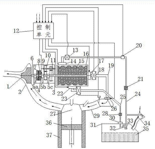
[0015] Such as figure 1 As shown, the automobile itself has an engine exhaust pipe 2 , a carbon canister 16 and a fuel tank 31 . A turbine 1 is placed in the middle of the engine exhaust pipe 2 inside of the automobile, and the center of the turbine 1 is collinear with the center of the engine exhaust pipe 2 . The turbine 1 is fixedly supported by the inner wall surface of the engine exhaust pipe 2 . The big end of the turbine 1 faces the direction of exhaust gas discharge, and the small end faces the direction of exhaust gas discharge.

[0016] There is a space between the turbine 1 and one end surface of the carbon canister 16 in the axial direction, and a clutch, a thrust device 4 and a speed reducer 10 are sequentially arranged in this space. Clutch is made up of clutch driving disc 7 and clutch driven disc 8, and speed reducer 10 is made up of the driving gear of speed reducer 10 and the output gear of speed reducer 10. The thrust device 4 is located between the clutch...


PUM


Abstract

The invention discloses a centrifugal type carbon tank desorption device and method for an exhaust gas turbine. By utilizing high-speed tail gas of an engine as power, a clutch and a speed reducer are mounted on a power transmission line; when active carbon adsorption capacity reaches the maximum saturation level, a carbon tank is driven by a transmission shaft to rotate, the adsorbed oil-gas is thrown out by centrifugal force; after oil-liquid is formed, the oil-liquid flows into an oil tank through an oil-liquid reflow pipe; when the carbon tank does not reach the saturation level, the active carbon is desorbed by launching pressure difference between the inner part of an air cylinder and the inner part of a combustion chamber, and the desorbed oil-gas flows into an air inlet pipeline of the engine by an oil-gas backflow pipe; and finally, the oil-gas is introduced into the combustion chamber to be used as fuel. By adopting two ways, the active carbon is desorbed, and energy of the tail gas is recycled; moreover, the desorption time is short, the efficiency is high, the desorption amount can be controlled, and liquid oil materials formed by the oil-gas can be recycled.

Description

technical field [0001] The invention belongs to the field of automobiles, and relates to a vehicle-mounted oil gas recovery system for refueling in automobiles, in particular to a carbon tank desorption technology for desorbing the oil gas in the carbon tank. Background technique [0002] With the continuous improvement of the requirements for vehicle emission indicators, each vehicle is equipped with an on-board refueling oil vapor recovery system (ORVR), and the carbon canister is an indispensable part of the system. Carbon tanks have the function of adsorbing volatile oil and gas, but the adsorption capacity of vehicle-mounted carbon tanks is limited and need to be desorbed in time, especially for hybrid vehicles. At present, the energy for the desorption of the carbon canister comes from the pressure difference in the engine cylinder or external energy, and the amount of desorbed oil and gas is uncontrollable during desorption, and some oil and gas cannot be desorbed, wh...

Claims


Application Information

Patent Timeline
Patent Type & Authority Applications(China)
IPC IPC(8): F02M25/08F01N5/04
CPCF01N5/04F02M25/08Y02T10/12
Inventor 何仁张恩慧
Owner 爱三(佛山)汽车部件有限公司
Learn More