A rotary kiln turbulent combustion method

A combustion method and rotary kiln technology, applied in the fields of combustion and environmental protection, can solve problems such as difficult combustion, excessive slag ignition rate, and appearance of returned material at the rotary kiln head, so as to improve heat and mass transfer performance, improve combustion performance, Effect of improving combustion performance

Active Publication Date: 2018-07-03
乐国明
View PDF6 Cites 0 Cited by
  • Summary
  • Abstract
  • Description
  • Claims
  • Application Information

AI Technical Summary

Problems solved by technology

[0003] However, the existing rotary kiln combustion waste has the following disadvantages: the excess coefficient of combustion air in the rotary kiln is high; the combustion effect of solid waste in the rotary kiln is not good, and the combustion is not easy to control; Occasionally, the ignition loss rate exceeds the standard, the rotary kiln head is not well sealed, and the rotary kiln head has returned material, etc.

Method used


Image

  • A rotary kiln turbulent combustion method
  • A rotary kiln turbulent combustion method
  • A rotary kiln turbulent combustion method

Examples


Embodiment approach 1

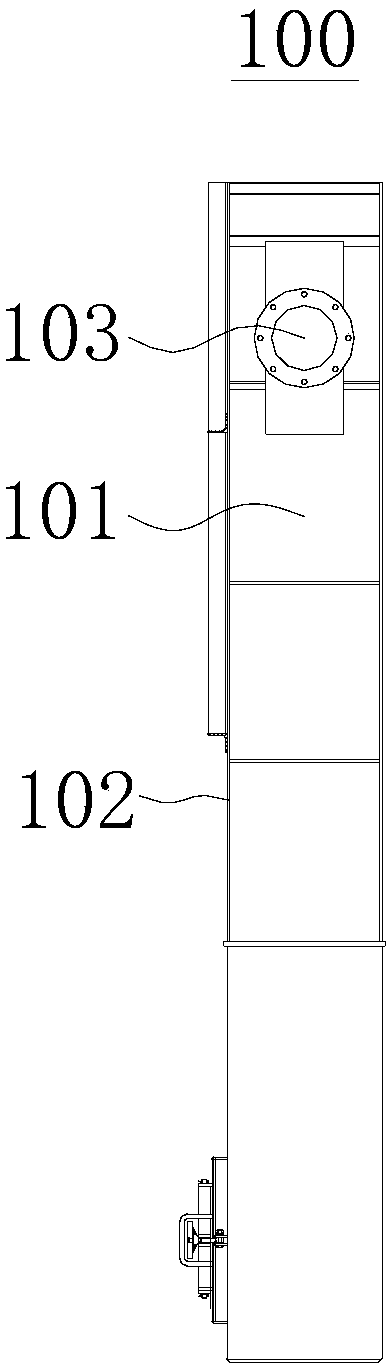
[0048] refer to figure 1 As shown, Embodiment 1 of the present invention provides a kiln head cover 100 , including a side wall 101 and an end cover 102 .

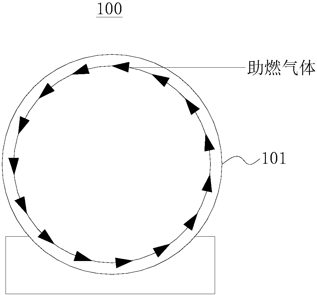
[0049] The side wall 101 and the end cover 102 enclose a receiving chamber with an open end, and the side wall 101 is provided with an air inlet 103 . Gas is passed into the kiln head cover 100 from the air inlet 103, and the movement direction of the gas is tangent to the inner surface of the side wall 101, and the gas can rotate in the kiln head cover 100 (such as figure 2 shown).

[0050] The side wall 101 can be rolled from a steel plate.

Embodiment approach 2

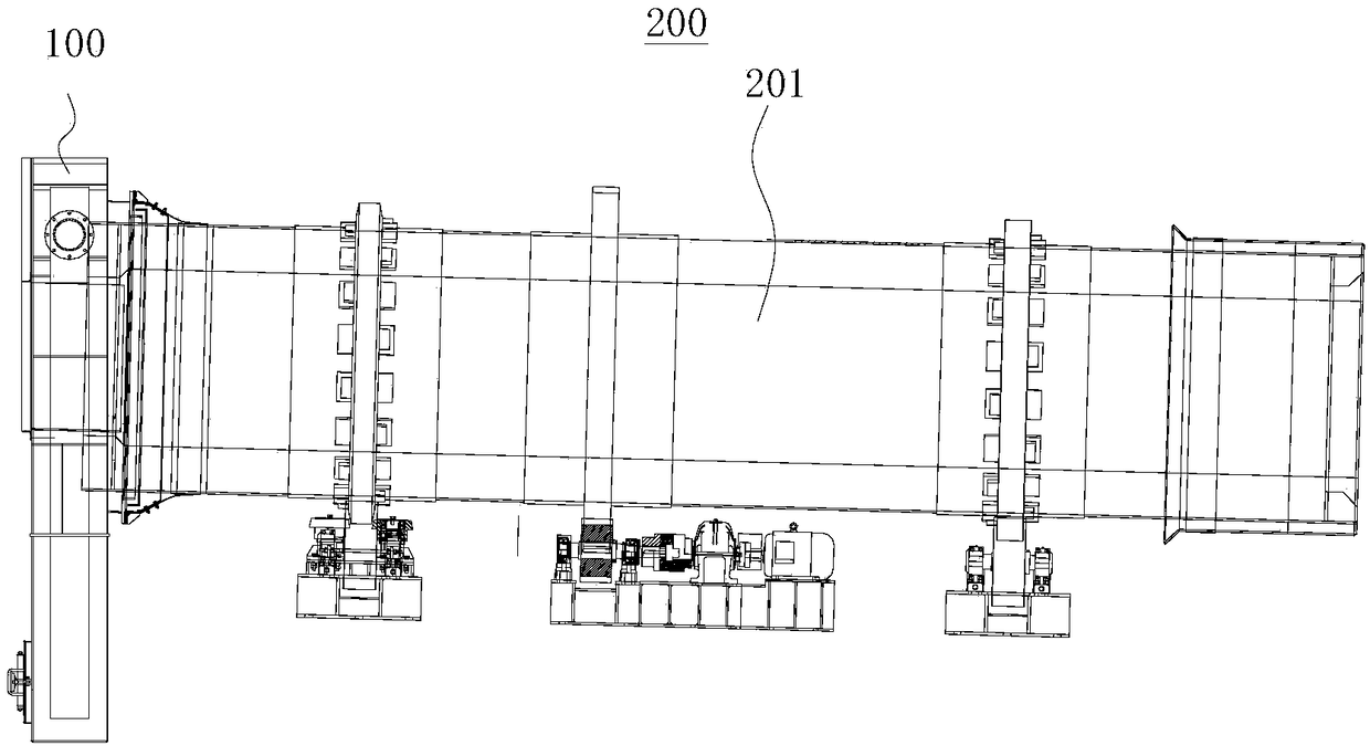
[0052] refer to image 3 As shown, Embodiment 2 of the present invention provides a rotary kiln 200 , including a cylinder body 201 and a kiln head cover 100 .

[0053] It should be noted that the kiln head cover 100 in this embodiment can adopt the kiln head cover 100 in the first embodiment, and its structure, working principle and technical effects can refer to the corresponding content in the first embodiment, which will not be described here. A detailed description.

[0054] The barrel 201 is a tubular structure with both ends open, and the interior of the barrel 201 is a combustion chamber. Materials can be incinerated in the combustion chamber.

[0055] The cylinder body 201 is formed by rolling and welding steel plates.

[0056] The kiln head cover 100 is arranged on one end of the cylinder body 201, the cylinder body 201 can rotate relative to the kiln head cover 100, a sealing device is arranged between the cylinder body 201 and the kiln head cover 100, and a circ...

Embodiment approach 3

[0061] Embodiment 3 of the present invention provides a combustion control method for a rotary kiln 200 , which is easy to operate and can fully burn waste.

[0062] It should be noted that the combustion control method of the rotary kiln 200 can be applied to the rotary kiln 200 in the second embodiment.

[0063] This rotary kiln 200 combustion control method comprises the following steps:

[0064] Heating step: before the operation of the rotary kiln 200, it is necessary to heat up the combustion chamber, ignite the burner of the rotary kiln 200, and gradually raise the temperature of the combustion chamber to between 650°C and 750°C according to the heating curve, preferably the temperature of the combustion chamber is raised to 700°C ℃ or so.

[0065] Ventilation step: When the temperature of the combustion chamber rises to the predetermined requirement, the combustion-supporting gas is introduced into the kiln head cover 100 from the air inlet 103 of the kiln head cover ...


PUM


Abstract

The invention provides a rotary kiln turbulent combustion method, a kiln head cover and a rotary kiln, and belongs to the technical field of combustion and environmental protection. The turbulent combustion method includes the steps of heating, ventilating and feeding. A combustion chamber needs to be heated before operation of the rotary kiln, and the temperature of the combustion chamber is raised to 650-750 DEG C. When the temperature of the combustion chamber is raised to a preset value, combustion-supporting gas is connected into the kiln head cover from the side wall of the kiln head cover, the moving direction of the combustion-supporting gas is tangent to the inner surface of the kiln head cover, and the combustion-supporting gas can rotate at a high speed and then enters the combustion chamber so that a turbulent environment can be formed inside the combustion chamber; and then waste is thrown into the combustion chamber, the amount of the waste thrown in at the beginning accounts for 8%-10% of the maximum processing capacity of the combustion chamber, and after combustion is made stable, the input of the waste is increased gradually. The rotary kiln turbulent combustion method is easy to operate. Under the turbulent environment condition, the waste can be fully burnt, the diffusion speed of turbulent combustion flames is high, the burning rate is also high, and the combustion performance and economic performance of a rotary kiln incinerator are greatly improved and perfected by means of turbulent combustion.

Description

technical field [0001] The invention relates to the technical field of combustion and environmental protection, in particular to a turbulent combustion method of a rotary kiln. Background technique [0002] A large amount of domestic garbage and waste are produced every day in the country. Most of these domestic garbage and waste contain toxic and harmful substances. If they are discharged indiscriminately, they will pollute the environment. Therefore, these wastes must be treated before they can be discharged. Hazardous waste treatment tasks are heavy, and the form and composition of hazardous waste are complex. Currently, rotary kilns are mainly used to incinerate solid waste. [0003] However, the existing rotary kiln combustion waste has the following disadvantages: the excess coefficient of combustion air in the rotary kiln is high; the combustion effect of solid waste in the rotary kiln is not good, and the combustion is not easy to control; Occasionally, the igniti...

Claims


Application Information

Patent Timeline
IPC IPC(8): F27B7/00F27B7/34F27B7/36F27B7/42
CPCF27B7/00F27B7/34F27B7/36F27B7/42
Inventor 乐国明
Owner 乐国明
Why Eureka
Try Eureka