Optical fiber grating strain sensor calibration and wear detection system

A grating sensor, strain sensor technology, applied in instruments, measuring devices, optical devices, etc., can solve problems such as low accuracy, and achieve the effect of sensitivity guarantee and accurate calibration method

Inactive Publication Date: 2017-08-11
BEIJING INFORMATION SCI & TECH UNIV
View PDF5 Cites 29 Cited by
  • Summary
  • Abstract
  • Description
  • Claims
  • Application Information

AI Technical Summary

Problems solved by technology

However, at present, the strain measurement sensitivity of these two methods can only be based on the coefficient or theoretical value provided by the supplier, which is a general coefficient and has low accuracy.
[0004] So far, th

Method used


Image

  • Optical fiber grating strain sensor calibration and wear detection system
  • Optical fiber grating strain sensor calibration and wear detection system
  • Optical fiber grating strain sensor calibration and wear detection system

Examples


Embodiment Construction

[0025] Hereinafter, embodiments of the present invention will be described with reference to the accompanying drawings. In the drawings, the same reference numerals represent the same or similar components, or the same or similar steps.

[0026] The objects and functions of the present invention and methods for achieving the objects and functions will be clarified by referring to the exemplary embodiments. However, the present invention is not limited to the exemplary embodiments disclosed below; it can be implemented in various forms. The essence of the description is only to help those skilled in the relevant art comprehensively understand the specific details of the present invention.

[0027] The present invention is described in detail in conjunction with schematic diagrams. When describing the embodiments of the present invention in detail, for the convenience of explanation, the cross-sectional view showing the structure of the device will not be partially enlarged acc...


PUM

PropertyMeasurementUnit
Wavelengthaaaaaaaaaa

Abstract

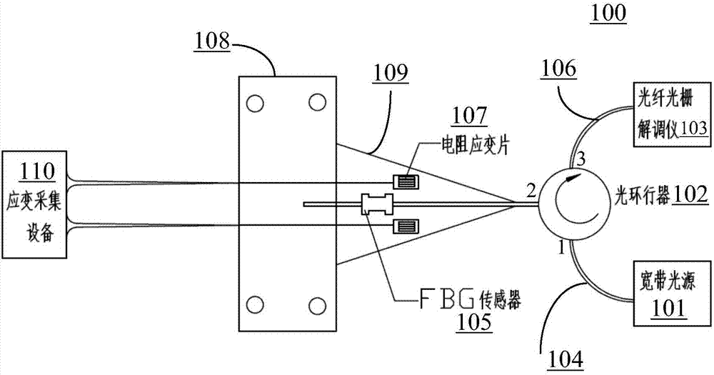
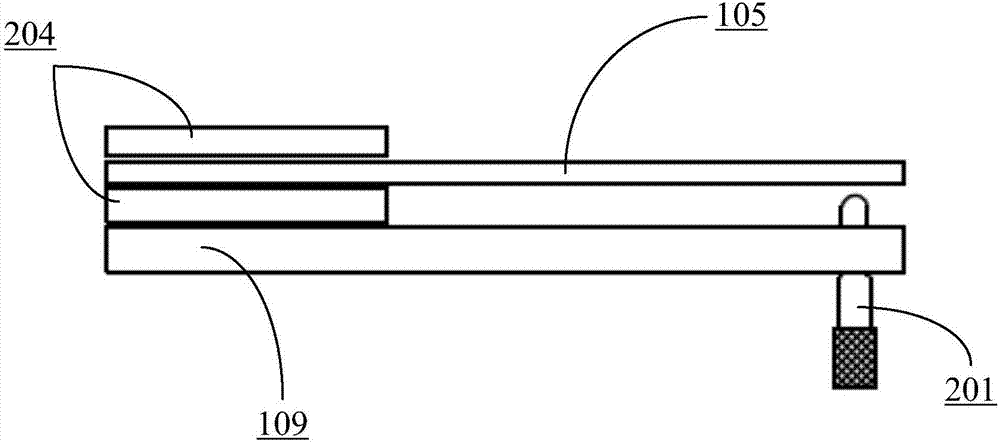
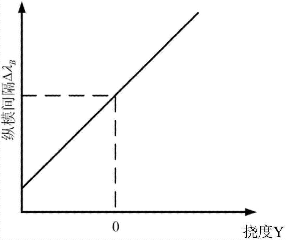
The present invention provides an optical fiber grating strain sensor calibration and wear life detection method, including the steps: a) building a testing system in which a broadband light source, an optical circulator, an optical fiber grating demodulation instrument, a single mode fiber, a Bragg optical fiber grating sensor, an optical fiber, a resistance strain gauge, a fixture, a constant strength cantilever beam and a strain acquisition device are connected in sequence; b) exerting loads on the constant strength cantilever beam through a linear actuator to subject the constant strength cantilever beam to produce strain; c) through the resistance strain gauge, acquiring the magnitude of the resistance change of the strain gauge; d) through the optical fiber grating demodulation instrument, accessing the peak translation of the reflected light of the Bragg optical fiber grating sensor generated by the strain caused by the constant strength cantilever beam; and e) calculating the relationship between the strain of the cantilever beam and the peak translation of the reflected light of the Bragg optical fiber grating sensor to realize the calibration and wear detection of the Bragg optical fiber grating sensor.

Description

technical field [0001] The invention relates to a fiber grating strain sensor calibration and fatigue detection system. Background technique [0002] Fiber Bragg grating is a kind of fiber optic passive device with milestone significance. Because of its unique advantages such as anti-electromagnetic interference, corrosion resistance, high insulation, wide range of measurement parameters, easy multiplexing and networking, and miniaturization, it has developed very rapidly. It has obtained important applications in the fields of electronic information, aerospace, materials and chemicals, construction and environment, underground pipe network, energy, military defense and so on. [0003] In the field of structural health monitoring, fiber grating sensors are widely used in the monitoring of strain parameters. At present, the metal packaged fiber grating sensor is usually pasted or welded on the surface of the structure, or the fiber grating is directly embedded in the composi...

Claims


Application Information

Patent Timeline
IPC IPC(8): G01B11/16
CPCG01B11/165
Inventor 祝连庆张钰明何巍董明利骆飞刘锋闫光
Owner BEIJING INFORMATION SCI & TECH UNIV
Why Eureka
Try Eureka