
Casing vibration shaft mouth monitoring detection equipment

A detection equipment and casing technology, applied in the direction of measuring devices, measuring ultrasonic/sonic/infrasonic waves, instruments, etc., can solve the problem of low first-time success rate of salvage construction, shorten oil well operation cycle, improve first-time success rate, and reduce operation cost effect

Inactive Publication Date: 2017-08-11
CHINA UNIV OF PETROLEUM (EAST CHINA)
View PDF6 Cites 2 Cited by
  • Summary
  • Abstract
  • Description
  • Claims
  • Application Information

AI Technical Summary

Problems solved by technology

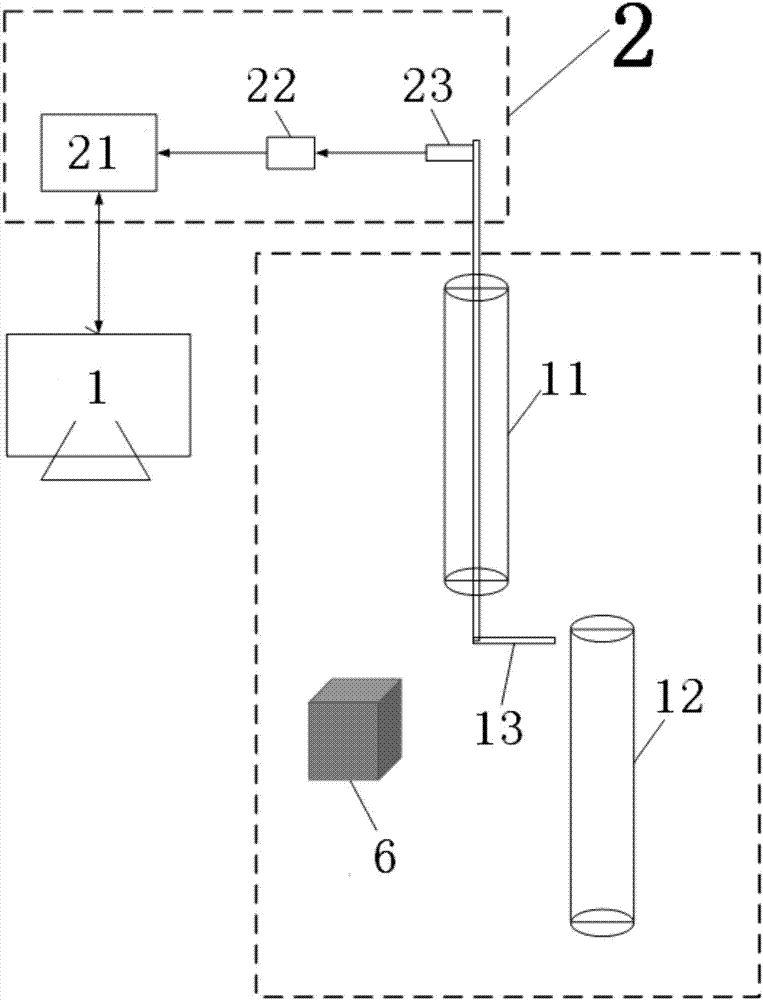
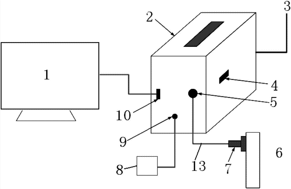
[0003] The purpose of the present invention is to overcome the above-mentioned problem of low success rate in salvage construction and provide a casing vibration wellhead monitoring and detection equipment

Method used


Image

  • Casing vibration shaft mouth monitoring detection equipment
  • Casing vibration shaft mouth monitoring detection equipment
  • Casing vibration shaft mouth monitoring detection equipment

Examples


Embodiment Construction

[0012] In order to make the technical problems solved by the present invention, the technical solutions adopted and the technical effects achieved clearer, the present invention will be further described in detail below in conjunction with the accompanying drawings and embodiments. It should be understood that the specific embodiments described here are only used to explain the present invention, but not to limit the present invention. In addition, it should be noted that, for the convenience of description, only parts related to the present invention are shown in the drawings but not all content.

[0013] The structure of the casing vibration wellhead monitoring and detection equipment in this embodiment is as follows: figure 1 and figure 2 As shown, it includes: one end of the metal probe 13 is magnetically attached to the micro-vibration sensor, and the other end is magnetically attached to the piezoelectric acceleration sensor 23 through the micro-vibration signal input ...


PUM


Abstract

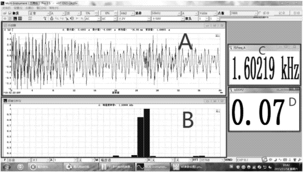
The invention discloses casing vibration shaft mouth monitoring detection equipment. The casing vibration shaft mouth monitoring detection equipment is characterized in that one end of a metal probe is magnetically attached to a micro-vibration sensor, and the other end of the metal probe is magnetically attached to a piezoelectric type acceleration sensor by a micro-vibration signal input port of a detector, and is in a data connection with a dynamic data acquisition device by a charger amplifier; the dynamic data acquisition device is used to input data in a computer terminal by a communication port, and the data is analyzed by matched software; after integrating processing of acquired acceleration signals is carried out twice, the acceleration signals are converted into amplitude signals; the amplitude signals are used to generate a sound real-time oscillogram; sound signals are played back in a sound box by an audio output port; Fourier operation of time domain signals is used to generate frequency domain signals to generate a spectrogram; by comparing the frequency domain signals with known object frequency domain information, a collided object type is identified.

Description

technical field [0001] The invention relates to the field of petroleum technology, in particular to casing vibration wellhead monitoring and detection equipment. Background technique [0002] Casing damage can result in overall pressure loss, thinning of production tubing, or the inability to run intervention tools. In actual operation, the one-time success rate of the fishing operation with the wrong casing is not high. The reason is that apart from complex well conditions and improper selection of fishing tools, one of the main reasons is that fishing is blind and it is difficult to achieve accurate fishing. In this case, the correctness of catching the falling objects in the well is particularly important. Contents of the invention [0003] The object of the present invention is to overcome the above-mentioned problem of low first-time success rate in salvage construction, and provide a casing vibration wellhead monitoring and detection device. [0004] The invention ...

Claims


Application Information

Patent Timeline
Patent Type & Authority Applications(China)
IPC IPC(8): G01H11/08
CPCG01H11/08
Inventor 李代林张令坦杨丹
Owner CHINA UNIV OF PETROLEUM (EAST CHINA)
Learn More