
Conductive heating device of conductive blank

A technology for conductive heating and blanks, applied in the field of conductive blank heating, can solve the problems of affecting the uniformity of the mechanical properties of thermoforming parts, aggravating the temperature difference of the blanks, and the heat generation of the blanks, etc., to improve energy utilization, reduce convection heat dissipation, low cost effect

Active Publication Date: 2017-08-11
FUJIAN UNIV OF TECH
View PDF7 Cites 0 Cited by
  • Summary
  • Abstract
  • Description
  • Claims
  • Application Information

AI Technical Summary

Problems solved by technology

However, during the conductive heating process, since the blank near the copper electrode conducts more heat to the copper electrode than the middle area, the temperature of the blank near the copper electrode is lower, and the temperature of the middle area far away from the copper electrode is higher.
At the same time, the resistivity of the blank increases with the increase of temperature. Therefore, the resistivity of the material in the area close to the copper electrode is low, and the resistivity of the material in the middle area away from the copper electrode is large. According to Joule's law, the blank in the area close to the copper electrode The calorific value is small, and the calorific value of the middle area away from the copper electrode is large, which further aggravates the temperature difference between the middle area of ​​the conductive heating blank and the blank near the copper electrode area. Therefore, under natural conditions, the temperature distribution of the conductive heating blank is The temperature in the middle area is high, and the temperature in the area close to the copper electrode is low, which affects the uniformity of the overall temperature of the blank and the mechanical properties of the subsequent hot-formed parts

Method used

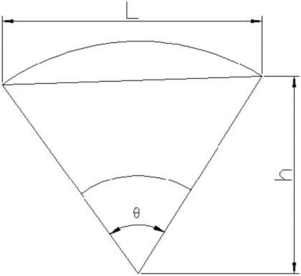

Image

  • Conductive heating device of conductive blank
  • Conductive heating device of conductive blank
  • Conductive heating device of conductive blank

Examples


Embodiment Construction

[0018] The present invention and the technical solutions in the embodiments of the present invention will be clearly and completely described below in conjunction with the accompanying drawings.

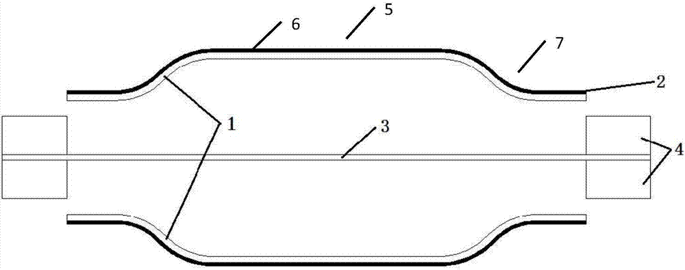
[0019] Such as figure 1 As shown, a conductive blank heating device includes a pair of oppositely arranged copper electrodes 4, a conductive blank 3 is installed between the copper electrodes 4, and a semi-closed cylindrical structure heat preservation device with openings at both ends is arranged around the conductive blank 3. A device 5, the inner surface of the heat preservation device 5 is an inner reflective layer 1 with low absorption rate and high reflectance rate, and the inner reflective layer 1 is wrapped with an outer energy storage layer 2 for thermal insulation and energy storage. The inner reflective layer 1 has a thickness of 0.1 mm to 2 mm, and the outer energy storage layer 2 has a thickness of 1 mm to 10 mm.

[0020] The middle part of the heat preservation device ...


PUM


Abstract

The invention discloses a conductive heating device of a conductive blank. The conductive heating device comprises a pair of copper electrodes arranged opposite to each other, wherein the conductive blank is arranged between the copper electrodes, a semi-closed structured heat preservation device is arranged around the conductive blank, two ends of the semi-closed structured heat preservation device are opened, an energy storage part is arranged at a middle part of the heat preservation device, the distance between each position in the energy storage part and a surface of the conductive blank is equal, shrinkage parts are respectively arranged at two ends of the heat preservation device, the distances between the shrinkage parts and the surface of the conductive blank are gradually reduced, and outer edges of the shrinkage parts are near to the copper electrodes. By an unequal heat transfer method, the conductive heating temperature uniformity of the conductive blank is achieved, the convection between the conductive blank and air is reduced, convection heat dissipation of the blank is reduced, the energy loss of the blank is reduced, and the energy utilization ratio is improved; and the device is simple to manufacture and convenient to install, is low in cost and is applicable to blanks with different shapes and sizes.

Description

technical field [0001] The invention belongs to the field of heating a conductive blank, and relates to a conductive heating device for a conductive blank. Background technique [0002] The heating of the billet is the first step in hot forming, and the uniformity of its temperature has an important impact on the performance of the final part. At present, industrial production mainly uses a box furnace or a roller hearth furnace to complete the heating of the billet. This heating method has the advantages of good overall temperature uniformity of the billet, but its heating rate is slow, the efficiency is low, the floor area is large, the cost is high, and it is flexible. Poor sex. As an alternative heating method, induction heating has the advantages of fast heating rate and high efficiency, but it is limited by the shape of the induction coil, that is, a coil of one shape can only heat a billet of a specific shape, and when the temperature of the material reaches After t...

Claims


Application Information

Patent Timeline
Patent Type & Authority Applications(China)
IPC IPC(8): H05B3/00
CPCH05B3/0004Y02P10/25
Inventor 梁卫抗王乾廷陈鼎宁王建杰
Owner FUJIAN UNIV OF TECH
Learn More