Electric spindle capable of realizing automatic tool changing and provided with build-in shank

An automatic tool change and built-in technology, which is applied in the direction of metal processing machinery parts, maintenance and safety accessories, metal processing equipment, etc., can solve the problem that the radial machining accuracy and processing efficiency are difficult to guarantee at the same time, affecting the working efficiency and service life of the spindle , Inability to realize online automatic tool change and other problems, to achieve the effects of increased structural strength, reduced maintenance costs, and reduced rolling and sliding friction

Pending Publication Date: 2017-08-15
岳阳市显隆电机有限公司
View PDF7 Cites 7 Cited by
  • Summary
  • Abstract
  • Description
  • Claims
  • Application Information

AI Technical Summary

Problems solved by technology

[0002] At present, high-speed electric spindles generally adopt the principle of asynchronous motors, and obtain various rotational speeds by changing the current frequency and excitation voltage input to the stator windings of the motor. Cooling measures. When the electric spindle is working at high speed, the temperature rises quickly. Because it is in a high temperature state for a long time, it will affect the working efficiency and service life of the spindle. The rotor magnetic parts are made of die-cast aluminum, which produces obvious heat, and indirectly causes the stator coil to heat up. , reduce the overall work efficiency, reduce the life of the electric spindle, and increase maintenance costs. The high-speed tool adopts a collet type, and the collet is connected to the rotor shaft bully through a threaded connection, and then the opening and closing of the tool is controlled by the air pressure. This clamping method The disadvantage is that the radial constraint and radial rigidity of the tool are small. When performing large-scale milling, it is difficult to guarantee the radial machining accuracy and machining efficiency at the same time, and the axial machining depth is limited. At the same time, this clamping method cannot realize online automatic change. Knife is not convenient for production and use, and its practicability is poor

Method used


Image

  • Electric spindle capable of realizing automatic tool changing and provided with build-in shank
  • Electric spindle capable of realizing automatic tool changing and provided with build-in shank
  • Electric spindle capable of realizing automatic tool changing and provided with build-in shank

Examples


specific Embodiment approach

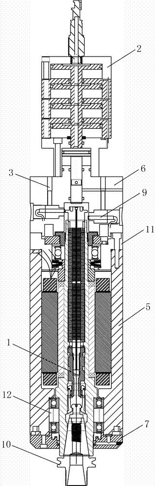
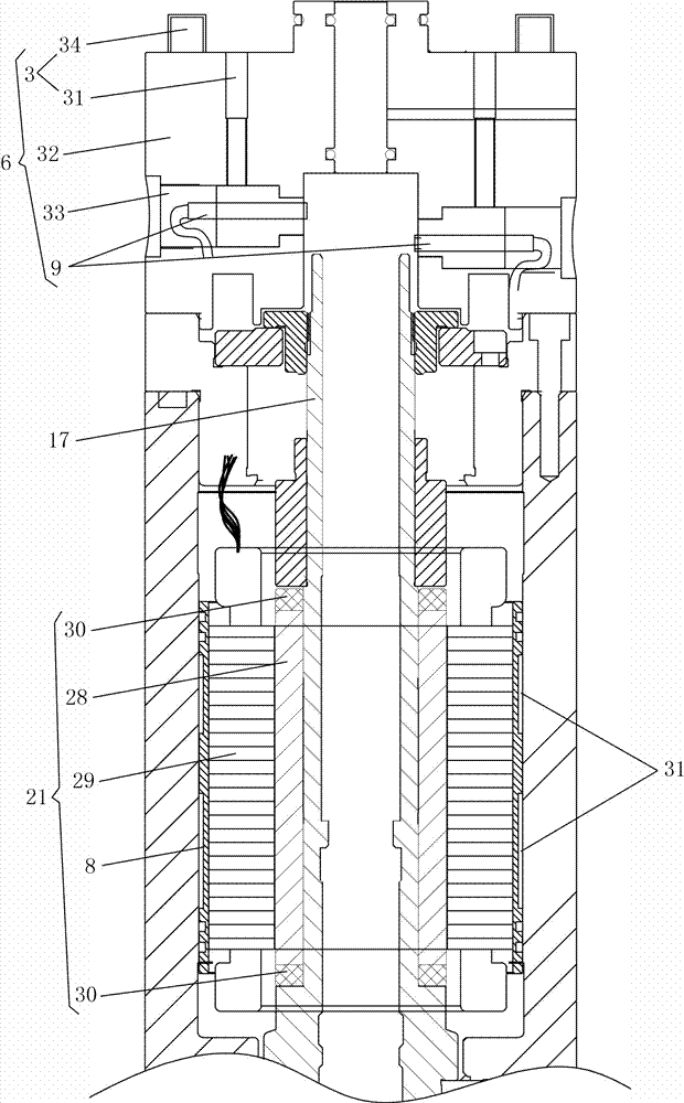
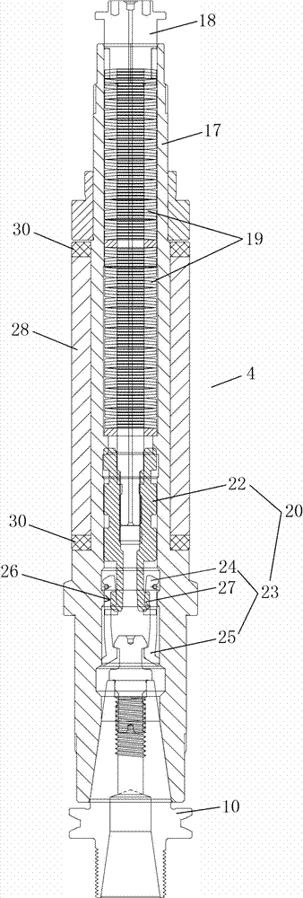
[0028] Such as Figure 1-8 As shown, an electric spindle with a built-in tool holder for automatic tool change includes a main shaft body 1 and a drive device 2 that provides power and is transmission-connected to the main shaft body 1. The main shaft body 1 is provided with a cooling mechanism 3. The spindle body 1 includes a spindle housing 5 with a spindle assembly 4 press-fitted therein, a rear seat 6 and a dust cover 7 respectively arranged at both ends of the spindle housing 5, and the spindle assembly 4 is fixedly installed through a cooling copper sleeve 8 In the spindle housing 5, the rear seat 6 is provided with a detection device 9 and a control device, one end of the spindle assembly 4 is connected to the driving device 2 in a transmission manner, and the other end is detachably connected to the knife The handle 10 is connected.

[0029] Wherein, the two ends of the main shaft body 1 respectively include a rear bearing assembly 11, a front bearing assembly 12 and ...


PUM


Abstract

The invention relates to an electric spindle capable of realizing automatic tool changing and provided with a build-in shank. A spindle body is provided with a cooling mechanism and comprises a spindle box, a back seat and a dust cover; spindle assemblies are press-fitted in the spindle box; the back seat and the dust cover are arranged at two ends of the spindle box; the spindle assemblies are fixedly mounted in the spindle box through cooling copper sleeves; a detection device and a control device are arranged on the back seat; one end of each spindle assembly is in transmission connection with a driving device; and the other end of each spindle assembly is detachably connected with an external device. The electric spindle has the beneficial effects as follows: a stator coil outer sleeve is changed from a steel piece into a brass casting, a circulating water-cooling channel is added in the casting outer sleeve, the temperature is prevented from increasing too fast, the operation precision of the spindle is kept, a clamping jaw and the shank are organically combined, meanwhile, a built-in encoder connected with a control center is configured, functions of automatic tool changing, instant accurate stop and the like are realized, a rotor magnetic piece is in short-circuited connection through an end copper ring, the consumption is reduced, a steel angular contact ball bearing is replaced with a ceramic ball bearing, the friction and the heat are reduced, and the life is prolonged.

Description

technical field [0001] The invention relates to an electric spindle, in particular to an electric spindle with a built-in automatic tool change tool holder for high-speed milling and drilling of light precision engraving and milling machines and light machining centers. Background technique [0002] At present, high-speed electric spindles generally adopt the principle of asynchronous motors, and obtain various rotational speeds by changing the current frequency and excitation voltage input to the stator windings of the motor. Cooling measures. When the electric spindle is working at high speed, the temperature rises quickly. Because it is in a high temperature state for a long time, it will affect the working efficiency and service life of the spindle. The rotor magnetic parts are made of die-cast aluminum, which produces obvious heat, and indirectly causes the stator coil to heat up. , reduce the overall work efficiency, reduce the life of the electric spindle, and increas...

Claims


Application Information

Patent Timeline
Patent Type & Authority Applications(China)
IPC IPC(8): B23Q5/28B23Q11/12
CPCB23Q5/28B23Q11/12
Inventor 韦华才何雅文吴克刚
Owner 岳阳市显隆电机有限公司
Why Eureka
Try Eureka