
A three-dimensional grid structure and energy dissipation method for energy dissipation of a discharge gravity dam

A grid structure and gravity dam technology, applied in water conservancy engineering, marine engineering, construction, etc., can solve the problems of river bed damage and unstable flow state of downflow, and achieve the effect of reducing additional damage and stable flow state.

Active Publication Date: 2020-11-06
SHANDONG UNIV
View PDF8 Cites 0 Cited by
  • Summary
  • Abstract
  • Description
  • Claims
  • Application Information

AI Technical Summary

Problems solved by technology

The main principle of energy dissipation in these ways is to generate a hydraulic jump, which converts the rapid flow from the drainage structure into a slow flow, and relies on the strong turbulence between the surface vortex generated by the hydraulic jump and the main flow at the bottom, shearing and mixing. Mixing is used to eliminate the energy of the water flow. Although the purpose of energy dissipation can be achieved, it also makes the flow state of the discharged water flow and its instability, which will cause additional damage to the river bed.

Method used


Image

  • A three-dimensional grid structure and energy dissipation method for energy dissipation of a discharge gravity dam
  • A three-dimensional grid structure and energy dissipation method for energy dissipation of a discharge gravity dam
  • A three-dimensional grid structure and energy dissipation method for energy dissipation of a discharge gravity dam

Examples


Embodiment 1

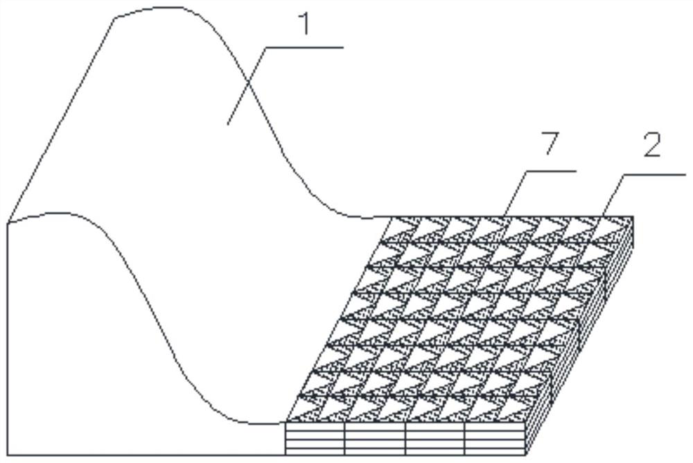
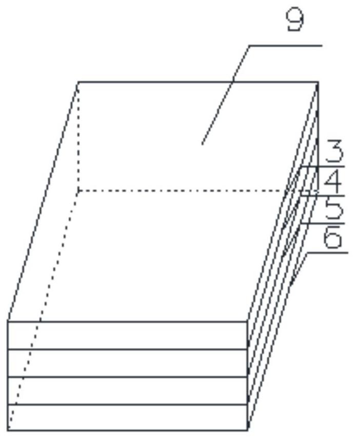
[0025] Such as Figure 1-Figure 4 As shown, a three-dimensional grid structure for the energy dissipation of the discharge gravity dam is installed at the bottom of the river channel of the discharge gravity dam 1, including four layers of grid grids, and each layer of grid grids includes grid parts and non-grid parts part, the non-grid part is composed of a tough braided mesh 7 with a roughness between 0.15 and 0.2; the four-layer grid grid is the first layer of grid 3, the second layer of Grid 4, third layer grid 5 and fourth layer grid 6; the first layer grid 3 and the third layer grid 5 are distributed in a triangle, the second layer grid 4 and the fourth layer The layer grids 6 are distributed in a rhombus shape.

[0026] Further, the grid part of the first layer of grid 3 and the third layer of grid 5 is a triangular grid, and the direction of the sharp angle of the triangular grid is the same as the direction of water flow, which can control the discharge of water in t...

Embodiment 2

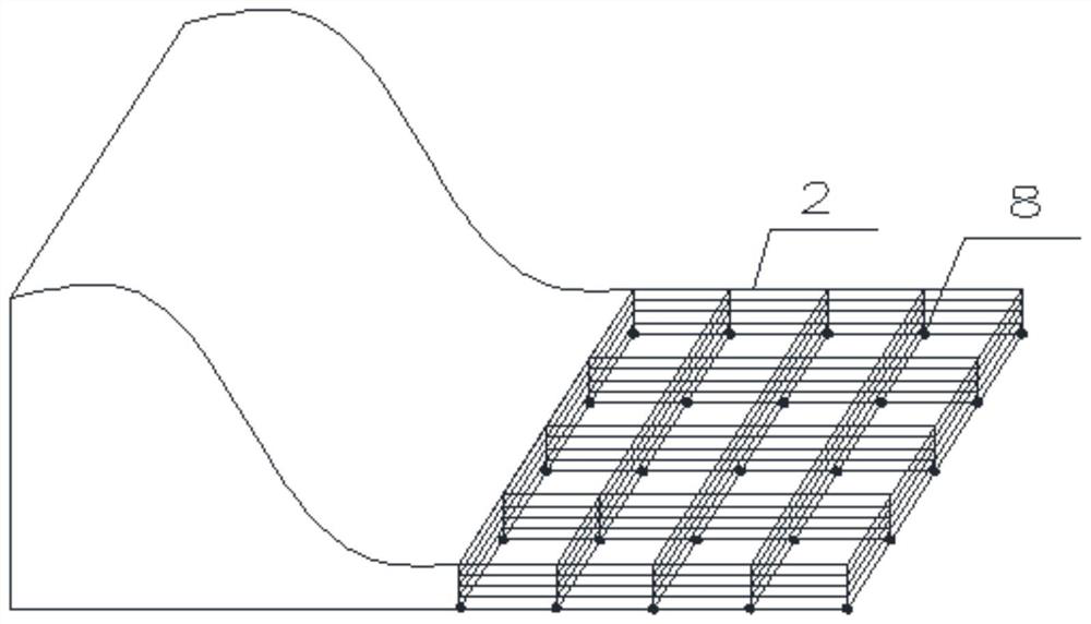
[0037] The three-dimensional grid structure 2 in Example 1 can be welded by steel for each layer of the single group of grids, and anchored to the downstream riverbed by anchors 8. The grid structures of each layer are supported by steel or concrete structures, and the grids at all levels The central African grid part is filled by the tough braided mesh 7 whose roughness is between 0.15 and 0.2. In a specific project, as long as the principle of energy dissipation is adopted, the use of materials can be adjusted appropriately according to the cost of the project when the strength is satisfied.

[0038] The accompanying drawings of the present invention are only schematic diagrams of each structure. In a specific project, the three-dimensional grid structure 2 can be welded and assembled by a single group of three-dimensional grid structures. The quantity of assembly and the scope of use can be viewed according to the specific conditions of the project. Depends on and is not li...


PUM


Abstract

The invention discloses an energy dissipation three-dimensional grating structure of a sluicing gravity dam. The energy dissipation three-dimensional grating structure is mounted at the bottom of a watercourse of the sluicing gravity dam and comprises four layers of grating grids. Each layer of grating grids comprises a grid part and a non-grid part which is formed by a tough woven net. The four layers of grating grids are sequentially the first layer grating, the second layer grating, the third layer grating and the fourth layer grating from top to bottom. The first layer grating and the third layer grating are distributed in a triangular mode, and the second layer grating and the fourth layer grating are distributed in a rhombic mode. By adoption of the three-dimensional grating structure, sluicing waterflow can depend on the multi-layer energy dissipation gratings, the vertical flowing speed can be decomposed out under the effect of gravity, a layered flowing energy dissipation effect is generated, and a flowing state is relatively stable.

Description

technical field [0001] The invention belongs to the technical field of energy dissipation for a discharge gravity dam in water conservancy and hydropower projects, and in particular relates to a three-dimensional grid structure and an energy dissipation method for a discharge gravity dam. Background technique [0002] In water conservancy projects, the discharge gravity dam is both a water retaining structure and a discharge structure, and its discharge methods include dam crest overflow and dam body discharge holes. In water conservancy projects, the discharge gravity dam can undertake tasks such as flood discharge, water delivery to the downstream, sand discharge, emptying of the reservoir and construction diversion. When the high-head discharge gravity dam discharges water, due to the high flow rate (up to 30-40m / s), the high-speed water flow generated will cause serious erosion damage to the downstream riverbed, and even cause bank slope collapse and dam failure. Theref...

Claims


Application Information

Patent Timeline
Patent Type & Authority Patents(China)
IPC IPC(8): E02B8/06
CPCE02B8/06
Inventor 李传奇马梦蝶王薇王德振肖学段明印崔佳伟荆倩婧杨幸子宋苏林
Owner SHANDONG UNIV
Learn More