Resistance increasing body and heading machine

A technology of blocking body and driver, which is applied in mining equipment, tunnels, earth-moving drilling and other directions, can solve the problems of unsuitable and limited use range of the roadheader, and achieve the effect of wide range of use and stable working performance.

Pending Publication Date: 2017-08-15
SANY HEAVY IND CO LTD (CN)
View PDF11 Cites 1 Cited by
  • Summary
  • Abstract
  • Description
  • Claims
  • Application Information

AI Technical Summary

Problems solved by technology

[0003] The present invention aims to provide a resistance-increasing body to solve the problem that the existing roadhead

Method used


Image

  • Resistance increasing body and heading machine
  • Resistance increasing body and heading machine
  • Resistance increasing body and heading machine

Examples


Example Embodiment

[0046] Example one

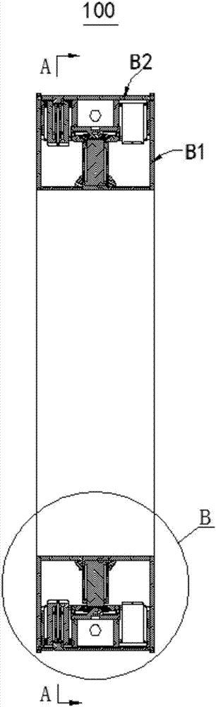
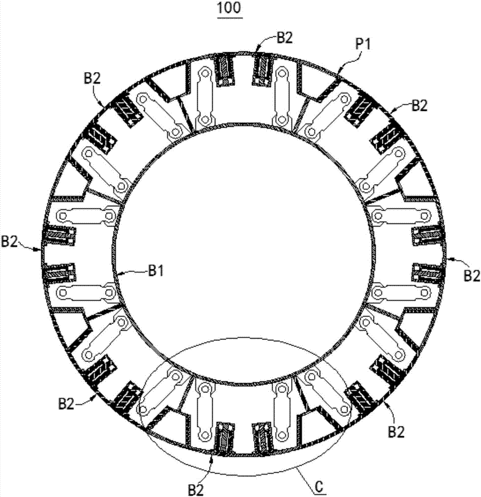
[0047] figure 1 It is a schematic diagram of the structure of the resistance increasing body 100 in the first embodiment of the present invention, and is shown in a cross-sectional view; figure 2 Yes figure 1 A cross-sectional view along the line A-A, the two figures together show the structure of the resistance increasing body 100 in this embodiment. Please refer to figure 1 , figure 2 The resistance increasing body 100 in this embodiment includes an annular support frame B1 and a plurality of resistance increasing mechanisms B2 distributed along the circumferential direction of the support frame B1. The outer surface of the support frame B1 is defined as the outer ring surface P1.

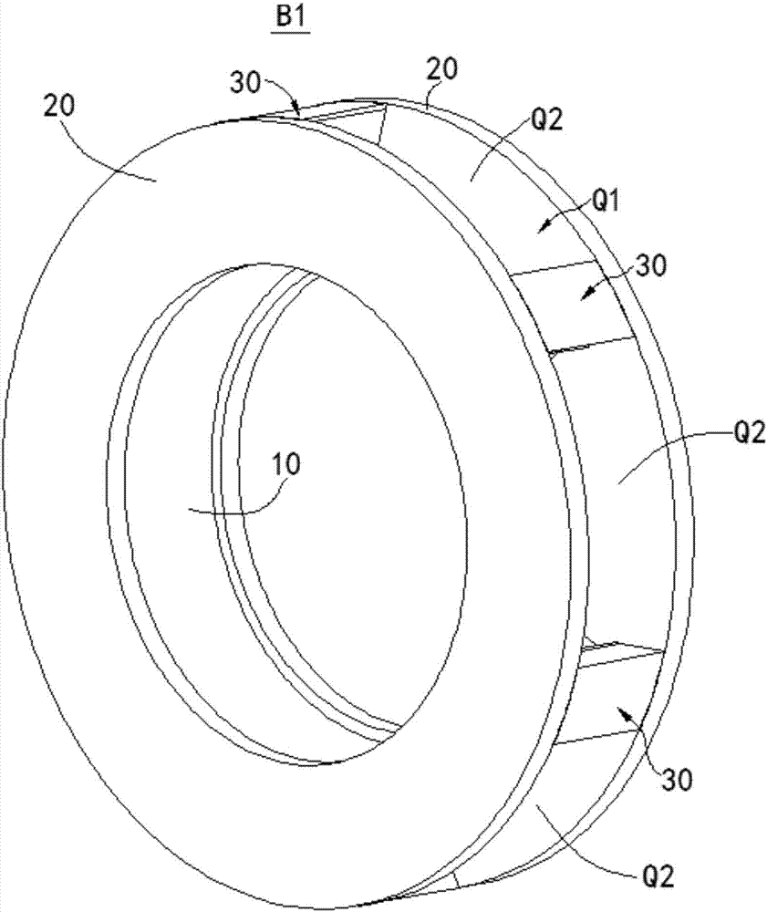
[0048] image 3 Yes figure 1 A perspective view of support frame B1 in. Please refer to image 3 The support frame B1 includes a cylindrical inner wall 10 and two annular end walls 20 respectively connected to the axial ends of the inner wall 10. The inner wall 10 and the two ...

Example Embodiment

[0057] Example two

[0058] Picture 12 It is a schematic diagram of the structure of the roadheader 010 in the embodiment of the present invention. See Picture 12 The roadheader 010 in this embodiment includes a cutter head 200 and a plurality of resistance increasing components 100a arranged at intervals along the axial direction. Adjacent drag-increasing components 100a are drivingly connected by an axial thruster 300. The cutter head 200 is connected to the outer end of the resistance increasing assembly 100a at the axial outer end. Optionally, there are two resistance increasing components 100a. The two resistance-increasing components 100a are connected to each other through an axial thruster 300, and the outer end of one of the resistance-increasing components 100a is connected to the cutter head 200 through an axial thruster 300. Each resistance increasing component 100a includes two resistance increasing bodies 100 connected along the axial direction. In other embod...


PUM


Abstract

The invention relates to the field of heading machinery and provides a resistance increasing body and a heading machine which aim at solving the problems that an existing heading device is not suitable for construction of stratums such as sand, cobble and hard rock, and the service range is limited. The resistance increasing body comprises an annular support frame and a plurality of resistance increasing mechanisms circumferentially distributed along the support frame. Each resistance increasing mechanism comprises a first driving device fixedly connected to the support frame and a friction piece slidably matched with the support frame. The first driving devices are in transmission connection with the friction pieces and arranged to be used for driving the friction pieces to extend out to the outer side of the outer annular surface of the support frame or draw back to the inner side of the outer annular surface. Each resistance increasing mechanism further comprises a second driving device fixedly connected to the corresponding friction piece and a shearing piece which is in transmission connection with the corresponding second driving device, and the shearing pieces are arranged to be capable of extending out to the outer sides of the outer surfaces of the friction pieces or drawing back to the inner sides of the outer surfaces of the friction pieces under driving of the second driving devices. The resistance increasing body and the heading machine have the beneficial effects that the various stratums such as clay, the sand, the cobble and the hard rock can be simultaneously adapted, and the adaption range is wide.

Description

Technical field [0001] The invention relates to the field of tunneling machinery, in particular to a resistance increasing body and a tunneling machine. Background technique [0002] The emergence of self-propelled tunneling construction technology and corresponding tunneling equipment overcomes the shortcomings of the existing shield method and pipe jacking method, and provides a new method for tunnel construction in increasingly narrow urban underground spaces. However, the existing self-propelled roadheader has the problem that it is not suitable for the construction of sandy soil, pebbles, hard rock and other stratum, and its use range is limited. Summary of the invention [0003] The invention aims to provide a resistance increasing body to solve the problem that the existing roadheader is not suitable for the construction of sandy soil, pebbles, hard rock and other stratums, and the application range is limited. [0004] Another object of the present invention is to provide a...

Claims


Application Information

Patent Timeline
IPC IPC(8): E21D9/10
CPCE21D9/1006
Inventor 王亮清吕传田
Owner SANY HEAVY IND CO LTD (CN)
Why Eureka
Try Eureka