
Micro-miniature centrifugal blood pump provided with self-adjusting blades

A micro-sized, blood pump technology, applied in blood pumps, medical science, hypodermic injection equipment, etc., can solve the problems that the boundary layer thickness, secondary flow and eddy current noise of the micro-small blood centrifugal pump cannot be well controlled, and achieve reduction Effects of small jet trail loss, reduced trail loss, and reduced eddy current noise

Active Publication Date: 2017-08-18
ZHEJIANG SCI-TECH UNIV
View PDF12 Cites 5 Cited by
  • Summary
  • Abstract
  • Description
  • Claims
  • Application Information

AI Technical Summary

Problems solved by technology

[0007] The purpose of the present invention is to provide a two-stage pump for the existing technology that cannot well control the boundary layer thickness, secondary flow and eddy current noise in the micro blood centrifugal pump, and cannot obtain adjustable blade installation angle blades for variable speed centrifugal pumps. The micro-centrifugal pump with blades, specifically, the suction surface of the first-stage blade has a winglet structure, and the second-stage impeller is a micro-small centrifugal blood pump with blades with automatic adjustment installation angle

Method used


Image

  • Micro-miniature centrifugal blood pump provided with self-adjusting blades
  • Micro-miniature centrifugal blood pump provided with self-adjusting blades
  • Micro-miniature centrifugal blood pump provided with self-adjusting blades

Examples


Embodiment Construction

[0034] The present invention will be further described below in conjunction with the accompanying drawings and embodiments.

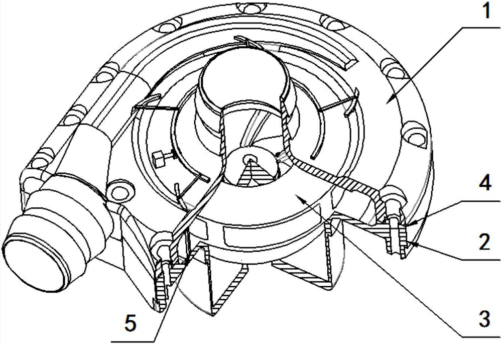
[0035] Such as figure 1As shown, a micro centrifugal blood pump with self-adjusting blades includes a front end cover 1, a rear end cover 2, a first-stage impeller 3 and a second-stage adjustable blade impeller 5; There is a gasket 4, and the front end cover 1 and the rear end cover 2 are connected by bolts; the front end cover 1, the rear end cover 2, the primary impeller 3 and the secondary adjustable blade impeller 5 are all arranged coaxially. The cavity between the front end cover 1 and the end surface of the first-stage impeller 3 is a pressurized water chamber, which is the inlet port of blood; the number of first-stage blades of the first-stage impeller 3 is Z=5.

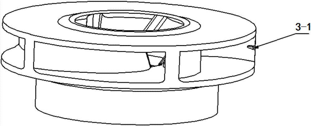
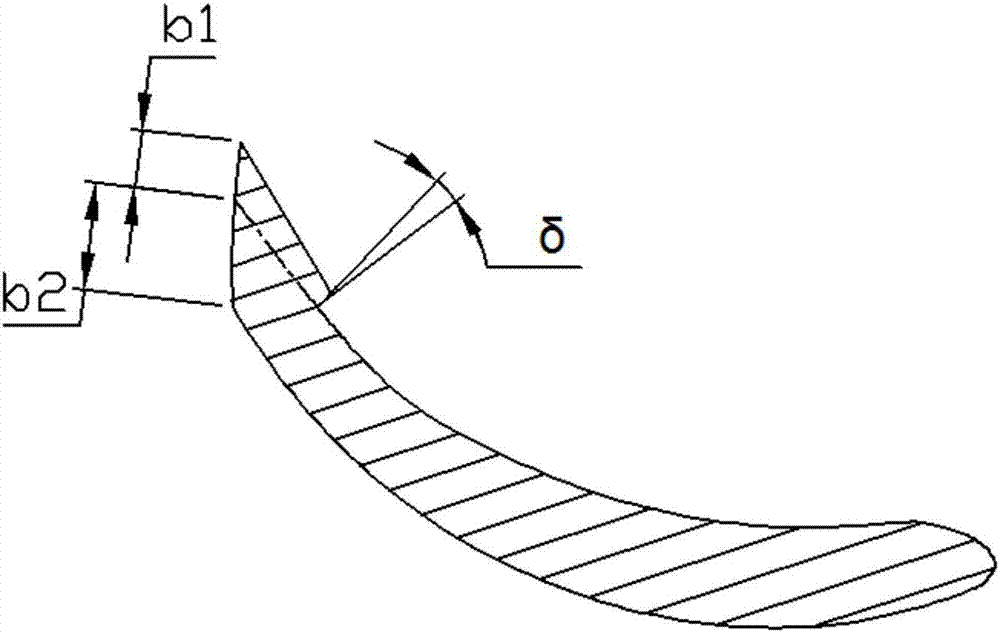
[0036] Such as figure 2 and 3 As shown, the suction surface of each first-stage blade of the first-stage impeller 3 is provided with a small wing 3-1 at the center of the height d...


PUM


Abstract

The invention discloses a micro-miniature centrifugal blood pump provided with self-adjusting blades, aiming at solving the problems in the prior art that boundary layer thickness, secondary flow and eddy noise in a micro-blood centrifugal pump cannot be well controlled. According to the micro-miniature centrifugal blood pump, a small wing is arranged on the force suction surface of each primary blade of a primary impeller; each secondary blade is fixed to a swinging blade by virtue of a cylindrical rod, and transmission pairs are defined by the cylindrical rods and a front end cover; an arc-shaped gear rack is arranged at the inner side of a driving ring; a gear at the output end of a control box is meshed with the arc-shaped gear rack; the ends, hinged with the driving ring, of various connecting rods are uniformly distributed in a circumferential direction of the driving ring; and in a direction from front edges to tail edges of swinging blades, division points, which serve as hinging ends of the swinging blades with the corresponding rods, are arranged on profile lines of the various swinging blades in accordance with corresponding sectional area ratios of the cylindrical rods at corresponding locations. According to the micro-miniature centrifugal blood pump provided by the invention, the secondary blades are different in attack angle, so that a requirement on adjusting blade mounting angles under conditions of different flow parameters such as different blood rates on different volute cross sections and the like can be satisfied.

Description

technical field [0001] The invention belongs to the field of fluid transportation, and relates to a miniature centrifugal blood pump with automatically adjustable blades, low noise, and low damage to blood cells, in particular to an automatic adjustment of blades according to a control box and a connecting rod system, and a small suction surface of the impeller blades. Micro centrifugal blood pump with wing structure. Background technique [0002] Pump is a kind of general-purpose machinery with a wide range of applications. It plays a huge role in human production and life. Pumps of different types and sizes are constantly being manufactured and used in various industries according to new application needs. middle. According to the different characteristic scales, pumps can be roughly divided into the following categories: conventional pumps, micro pumps and micro pumps. Among them, the characteristic scale range of micro-small pumps is roughly 1-50 mm, while the characte...

Claims


Application Information

Patent Timeline
IPC IPC(8): A61M1/10
CPCA61M60/205
Inventor 窦华书李昆航陈小平杨徽魏义坤张炜胡新建
Owner ZHEJIANG SCI-TECH UNIV
Learn More