Low-humidity temperature and humidity test tank

A humidity test, humidity temperature technology, applied in laboratory utensils, supporting utensils, shells or chambers, etc., can solve the problems of consuming gas energy, supporting a lot of work, and not being able to work for a long time.

Inactive Publication Date: 2017-08-18
SHANGHAI LINPIN INSTR
View PDF0 Cites 0 Cited by
  • Summary
  • Abstract
  • Description
  • Claims
  • Application Information

AI Technical Summary

Problems solved by technology

[0007] (1) The regeneration process of the rotary dehumidifier requires additional heat. Heating the air to regenerate the dry body consumes a lot of energy. At the same time, the temperature of the dried air will also be raised, which will affect the temperature of the laboratory;
[0008] (2) The adsorption dryer needs to be additionally connected to a compressed air source, and the adsorption material has a service life and needs to be replaced. There is a lot of supporting work and consumes gas energy, which has the effect of changing the air in the test and may violate the test requirements. At the same time The gas will be mixed with some tiny desiccant particles, which will pollute the test sample;
[0009] (3) Continuous freezing and dehumidification cannot work at low humidity for a long time

Method used


Image

  • Low-humidity temperature and humidity test tank
  • Low-humidity temperature and humidity test tank
  • Low-humidity temperature and humidity test tank

Examples


Embodiment Construction

[0031] Below in conjunction with accompanying drawing, the present invention will be further described as follows:

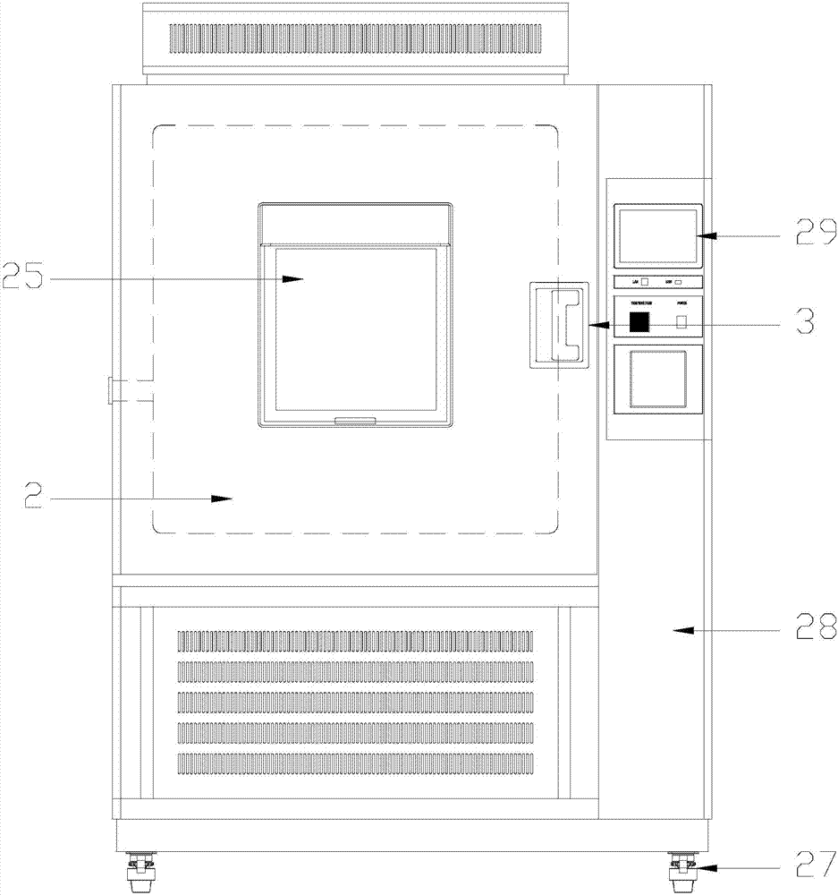
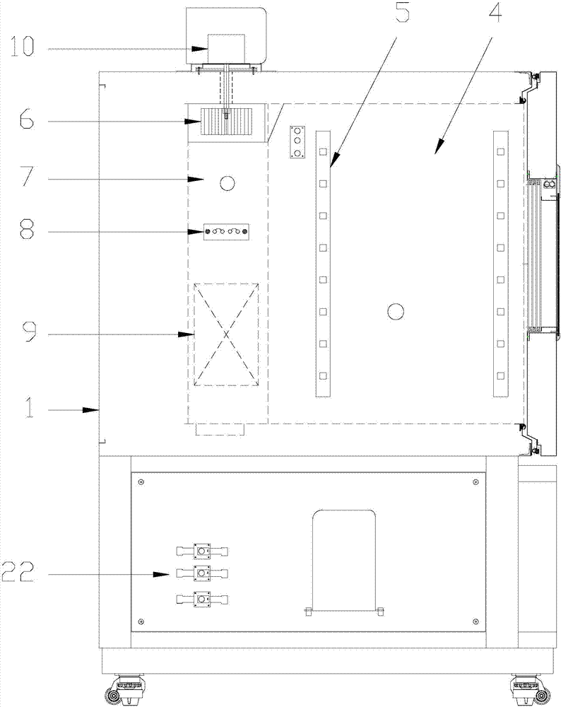
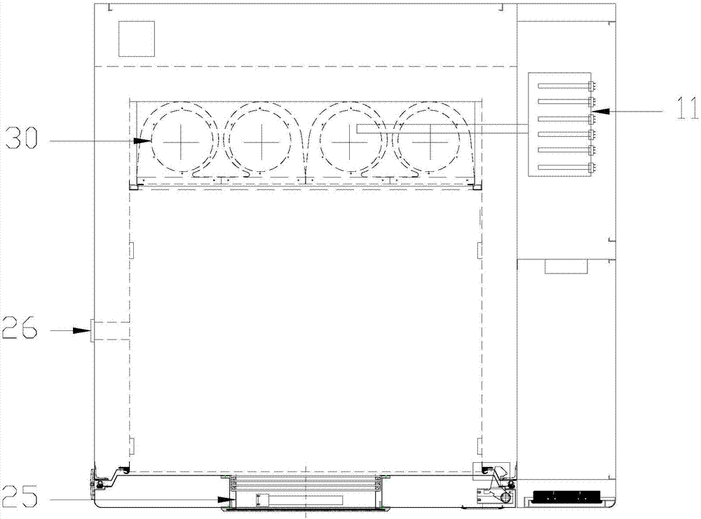
[0032] As shown in the drawings, the present invention includes: a box body 1, a box door 2 is arranged on the front end of the box body 1, a door handle 3 is installed on the box door 2, a test room 4 is provided at the front of the box body 1, and the test room 4 is equipped with a sample rack 5, and the rear of the box body 1 is provided with a circulating fan 6, a steam pipe 7, a heater 8, and an evaporator 9, and a circulating fan 6, a steam pipe 7, a heater 8, and an evaporator 9. Arranged in order from top to bottom, the circulation vane 6 is installed inside the fan volute 30, the circulation vane 6 is installed at the output end of the circulation motor 10, the circulation motor 10 is installed on the outer top of the box body 1, and the steam pipe 7 is connected to the humidification boiler 11 , the inlet end of the evaporator 9 is connected to the con...


PUM


Abstract

The invention relates to a low-humidity temperature and humidity test box, which comprises a box body, a box door is arranged on the front surface of the box body, a door handle is installed on the box door, a test room is arranged in the front part of the box body, a sample rack is installed in the test room, the box The rear part of the body is equipped with circulating fan blades, steam pipes, heaters, and evaporators in sequence from top to bottom. On the outer top, the steam pipe is connected to the humidifying boiler, the inlet end of the evaporator is connected to the condenser through a pipe, a filter is arranged between the evaporator and the condenser, the inlet end of the condenser is connected to the compressor, and the outlet end of the evaporator is respectively passed through a pipe Connect the evaporating pressure regulating valve and the four solenoid valves, and the evaporating pressure regulating valve and the four solenoid valves are set in parallel; the invention realizes that the evaporator will not freeze during long-term operation, and at the same time achieves the effect of saving energy and reducing consumption, and solves the problem that the air in the box is The problem of the effect of drying on the temperature of the laboratory.

Description

[0001] [technical field] [0002] The invention relates to the technical field of environmental test devices, in particular to a low-humidity temperature and humidity test chamber. [0003] [Background technique] [0004] At present, the existing temperature and humidity control generally adopts low-temperature dehumidification to control low-humidity points, but in order to ensure the continuity of humidity operation and prevent frosting of the evaporator, the evaporation pressure generally needs to be limited to a certain extent. But in this way, the low humidity point cannot be too low. Once the dew point of the relative humidity is close to or below the freezing point, the low humidity becomes uncontrollable. At this time, it is often necessary to use some external dehumidifiers to deal with it, and to modify the equipment. [0005] Common low-humidity dehumidification devices include: rotary dehumidifiers, adsorption dryers, and refrigeration dehumidification heat balance...

Claims


Application Information

Patent Timeline
Patent Type & Authority Applications(China)
IPC IPC(8): B01L1/02B01L7/00B01L9/00
CPCB01L1/025B01L7/00B01L9/00B01L2200/12B01L2300/185
Inventor 孙光林
Owner SHANGHAI LINPIN INSTR
Why Eureka
Try Eureka