

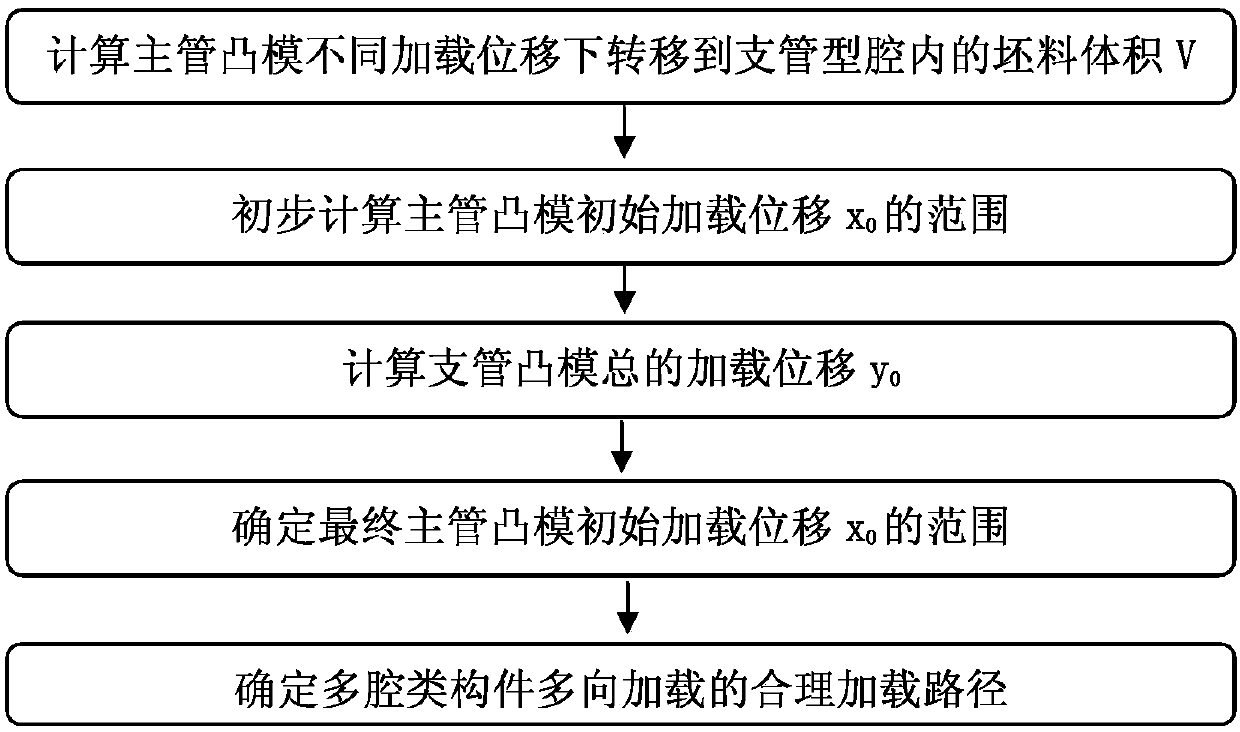
Method for determining loading path for achieving multi-way loading forming of multi-cavity component
A technology of loading path and determination method, which is applied in the direction of engine components, metal processing equipment, instruments, etc., can solve the problems of wasting time and increasing test cost, and achieve the effect of uniform metal flow, saving test cost and time, and reducing forming load
- Summary
- Abstract
- Description
- Claims
- Application Information
AI Technical Summary
Problems solved by technology
Method used
Image

Examples
Embodiment Construction
[0070] This embodiment is a method for determining a reasonable loading path for multi-directional loading forming of a multi-cavity component.
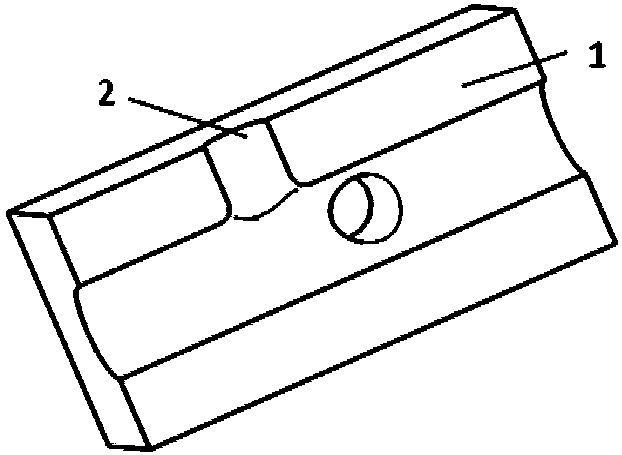
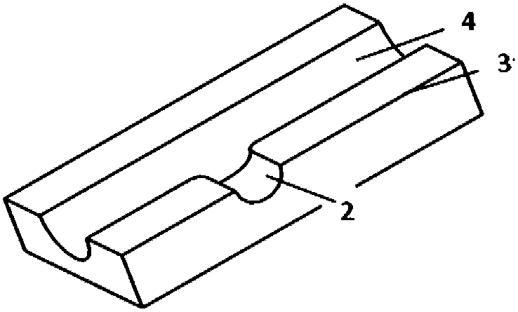
[0071] In this embodiment, the upper die 1 , the lower die 3 , the main pipe punch 6 and the branch pipe punch 7 are used to form a multi-cavity component by a loading forming method.
[0072] The upper die 1 is block-shaped, and the lower surface is a molded surface. There is a semicircular main pipe cavity 4 on this profile, which is used to shape the main pipe 9 of the multi-cavity component. There is a semicircular branch pipe cavity 2 on one side of the main pipe cavity; a circular branch pipe cavity is arranged on the upper surface of the upper die. Each of the branch pipe cavities 2 is connected to the main pipe cavity, and the centerlines of the two branch pipe cavities are perpendicular to the centerline of the main pipe cavity. The specific positions of the two branch pipe cavities are determined according to the shape of t...
PUM
| Property | Measurement | Unit |
|---|---|---|
| depth | aaaaa | aaaaa |
| depth | aaaaa | aaaaa |
Abstract
Description
Claims
Application Information