Tool magazine structure of direct-drive type servo motor controlled cutter disc

A servo motor and direct drive technology, which is applied in the field of the tool magazine structure of the direct drive servo motor to control the cutter head, can solve the problems of high operating noise, high wear rate, high cost of use, and complex structure, so as to improve the operating speed, Effects of reducing wear and noise and simplifying the structure

Active Publication Date: 2017-08-18
昆山北钜机械有限公司
View PDF4 Cites 3 Cited by
  • Summary
  • Abstract
  • Description
  • Claims
  • Application Information

AI Technical Summary

Problems solved by technology

[0003] Aiming at the problems of complex composition, high wear rate, high cost of use and high operating noise of the tool magazine of the processing machine, the present invention provides a tool magazine structure controlled by a direct-drive servo motor, which adopts a direct-drive Type servo motor directly drives the cutter head group, which makes the structure simple, low loss rate, low cost of use, and low operating noise

Method used


Image

  • Tool magazine structure of direct-drive type servo motor controlled cutter disc
  • Tool magazine structure of direct-drive type servo motor controlled cutter disc
  • Tool magazine structure of direct-drive type servo motor controlled cutter disc

Examples


Embodiment Construction

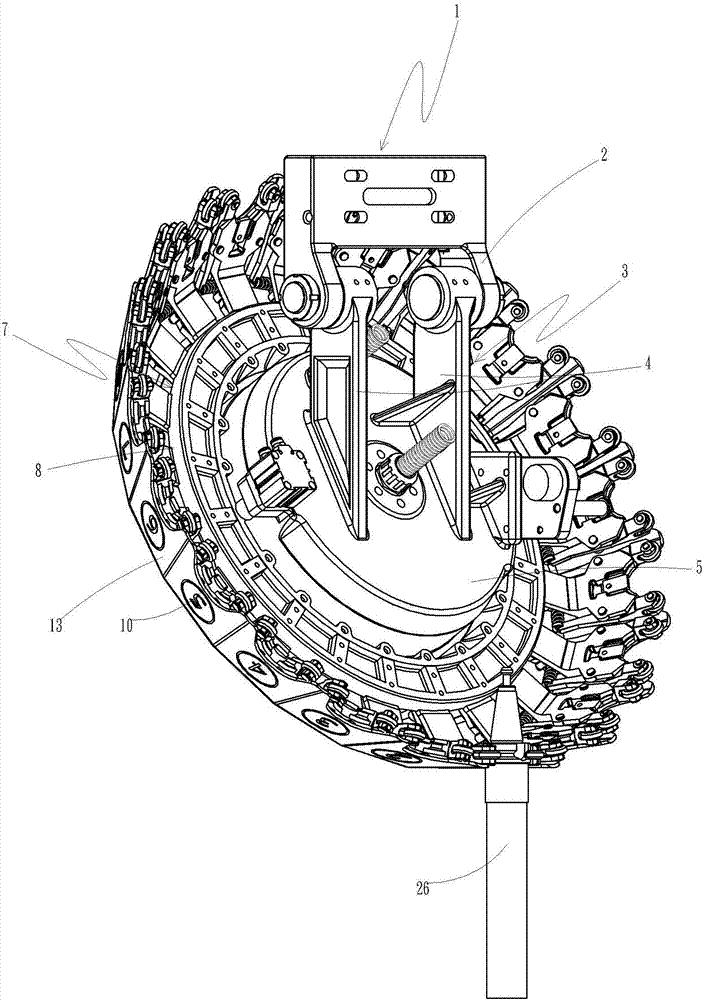
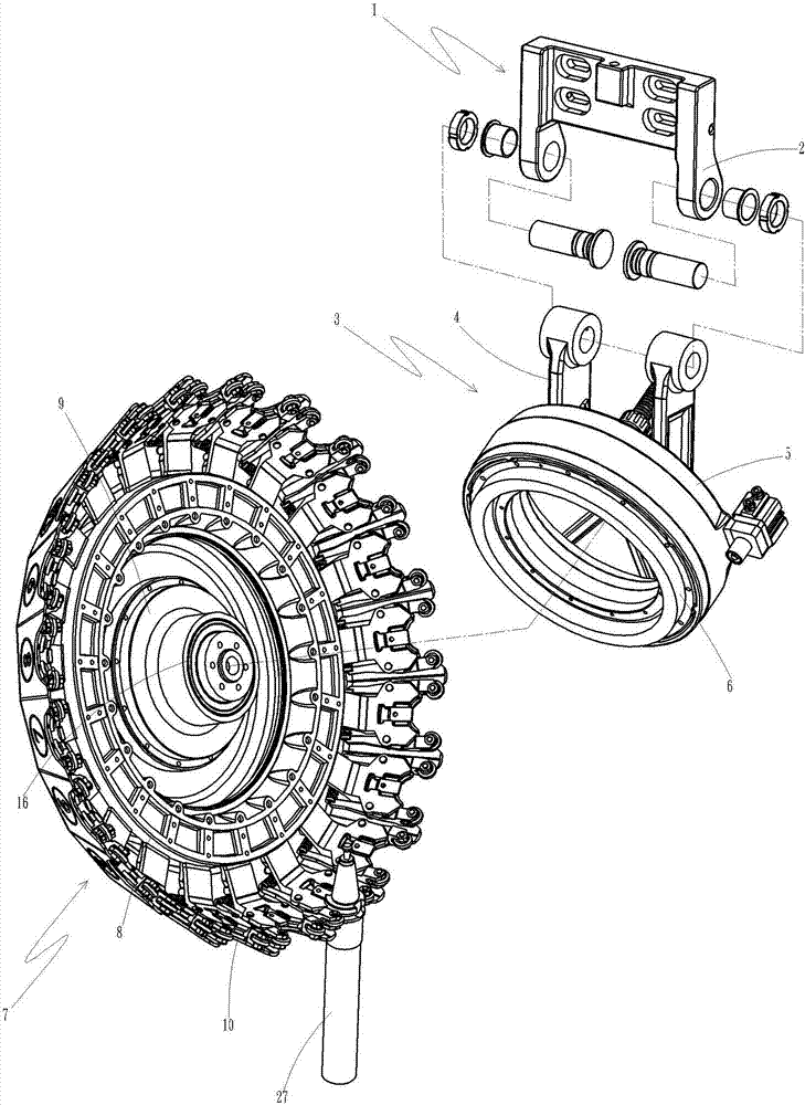
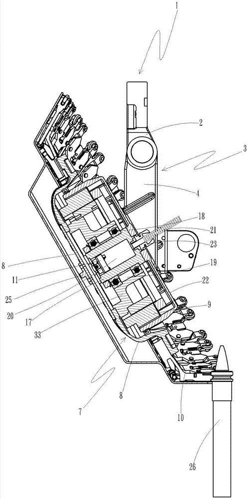
[0025] Direct drive servo motor controls the tool magazine structure of the cutter head, which is installed in a machine tool, see Figure 1 to Figure 5 , which includes:

[0026] A fixed seat 1, two pivot ears 2 are arranged on one side of the fixed seat 1, and the fixed seat 1 is combined with the machine tool;

[0027] A cutter head body 3, the cutter head body 3 is provided with a pivot arm 4, one end of the pivot arm 4 is fixed with a cutter head seat 5, and the cutter head seat 5 is provided with a direct drive servo motor 6, the pivot arm 4 Correspondingly pivotally combined with the pivot ear 2 of the fixed seat 1;

[0028] And a cutterhead group 7, the cutterhead group 7 is provided with a cutterhead 8, the rear side of the center position of the cutterhead 8 is fixed with a cutterhead mounting seat 9, and the peripheral ring of the cutterhead 8 is provided with some knife claws Group 10, each claw group 10 is respectively arranged with a cutter 26, the cutter head ...


PUM


Abstract

The invention provides a tool magazine structure of a direct-drive type servo motor controlled cutter disc. The tool magazine structure adopts a direct-drive type servo motor to directly drive a cutter disc rotating group, so that the tool magazine structure is simple in structure, low in loss coefficient, low in use cost and low in running noise. The tool magazine structure is arranged at a toolroom machine. The tool magazine structure is characterized in that the tool magazine structure comprises a fixing seat, a cutter disc seat body and a cutter containing disc group; two pivoting lugs are arranged on one side of the fixing seat; the fixing seat is combined with the toolroom machine; the cutter disc seat body is provided with pivoting arms; a cutter disc seat is fixedly arranged at the ends of the pivoting arms, and is internally provided with the direct-drive type servo motor; the pivoting arms are in pivoting combination with the pivoting lugs of the fixing seat correspondingly; the cutter containing disc group is provided with a cutter containing disc; a cutter disc mounting seat is fixedly arranged on the rear side of the center position of the cutter containing disc; a plurality of cutter and claw groups are annularly arranged at the periphery of the cutter containing disc; each cutter and claw group is provided with a cutter correspondingly; the cutter disc mounting seat is connected with the cutter disc seat body through the direct-drive type servo motor; and the cutter containing disc group is driven to rotate or stop by the direct-drive type servo motor electromagnetically.

Description

technical field [0001] The invention relates to the technical field of tool magazine structure, in particular to a tool magazine structure in which a direct-drive servo motor controls a cutter head. Background technique [0002] The cutter head driving structure of the existing tool magazine includes a tool changing mechanism and a tool magazine, and the tool magazine is provided with a rotating disk, the front end of the rotating disk is connected with a rotating cutter disk, and the rotating disk is provided with rollers, and the rotating knife The disc is driven by a motor to drive the chain wheel group, and then through the chain wheel group, the camshaft is linked to drive the cam to rotate, and the cam has a running track groove, and the rotation of the cam makes the roller of the rotating disc concave along the running track set by the cam. The operation of the grooves drives the rotating cutterhead connected to the front end of the rotating disk to move, which makes ...

Claims


Application Information

Patent Timeline
IPC IPC(8): B23Q3/157
CPCB23Q3/15706
Inventor 李双树
Owner 昆山北钜机械有限公司
Why Eureka
Try Eureka