Lifting wing for submersible

A technology of submersibles and transmissions, which is applied in the direction of underwater ships, special-purpose vessels, underwater operation equipment, etc., and can solve problems such as insufficient flexibility in rising and falling movements

Pending Publication Date: 2017-08-18
CHONGQING TONGLI INDAL
View PDF7 Cites 1 Cited by
  • Summary
  • Abstract
  • Description
  • Claims
  • Application Information

AI Technical Summary

Problems solved by technology

[0003] Today's underwater submersibles generally ascend and descend only by the drainage and water intake of the ballast water tank, so the ascending and descending movements are not flexible enough

Method used


Image

  • Lifting wing for submersible
  • Lifting wing for submersible
  • Lifting wing for submersible

Examples


Embodiment Construction

[0021] The preferred embodiments of the present invention will be described in detail below with reference to the accompanying drawings.

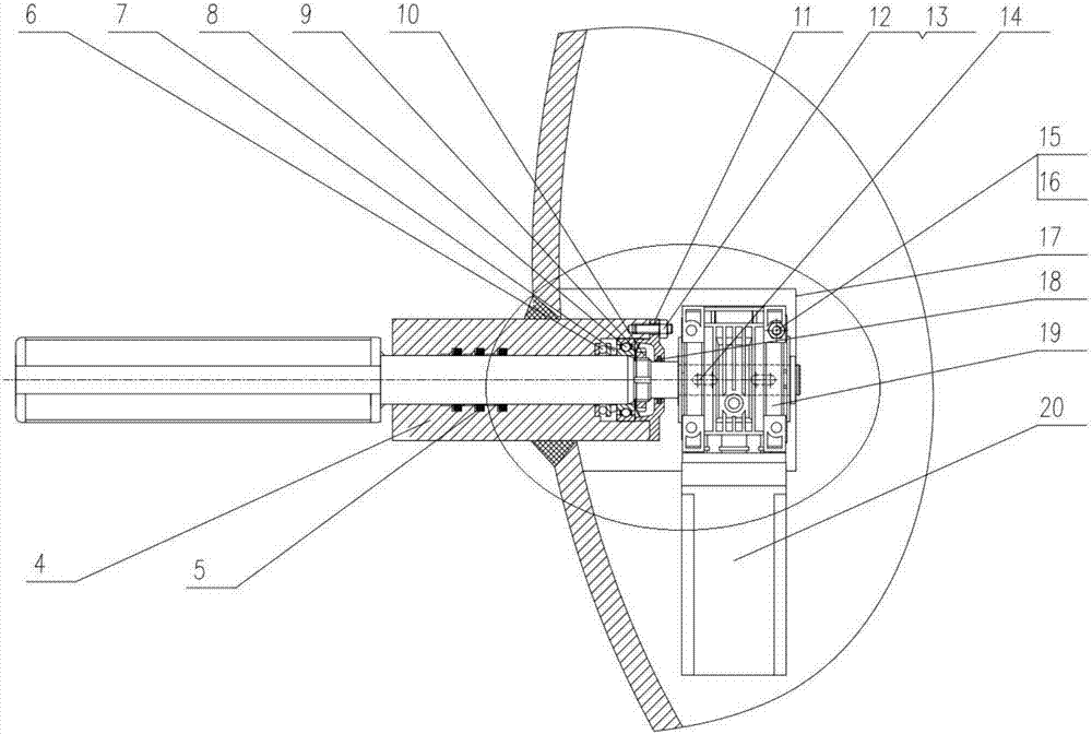
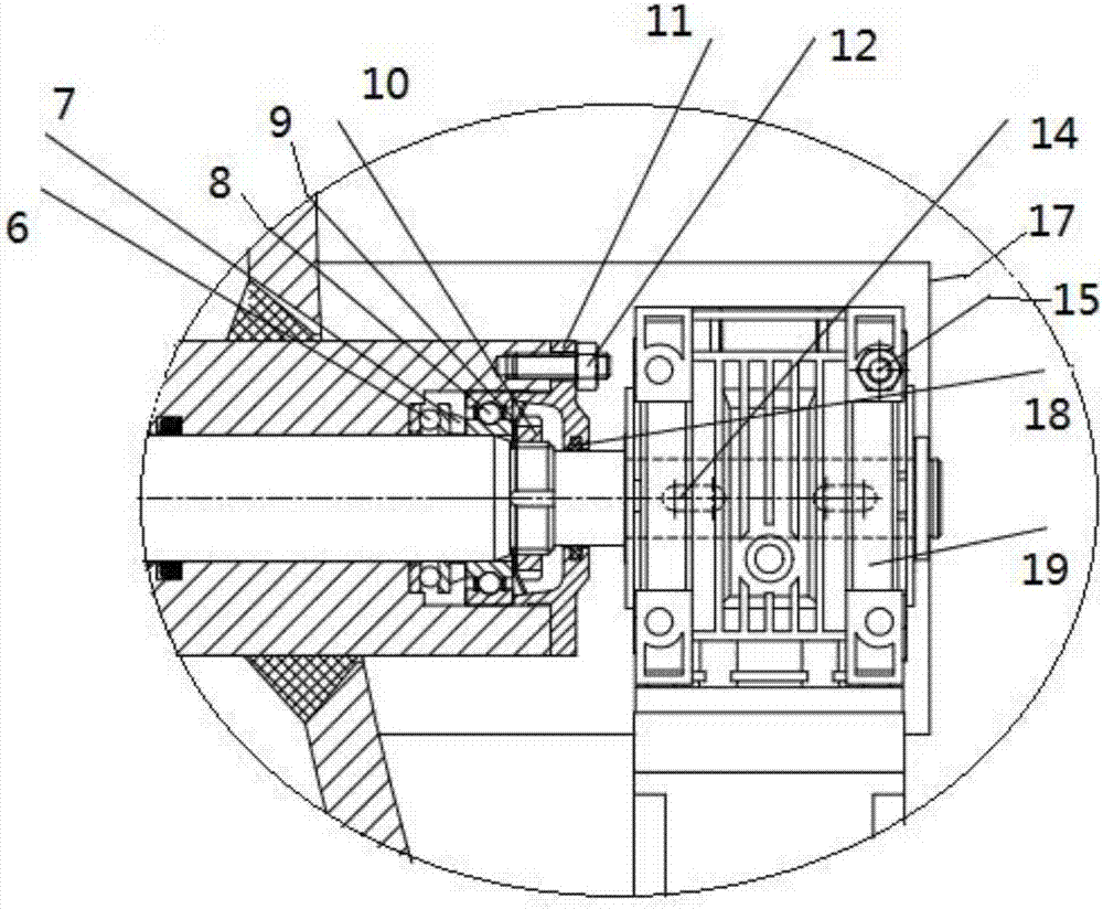
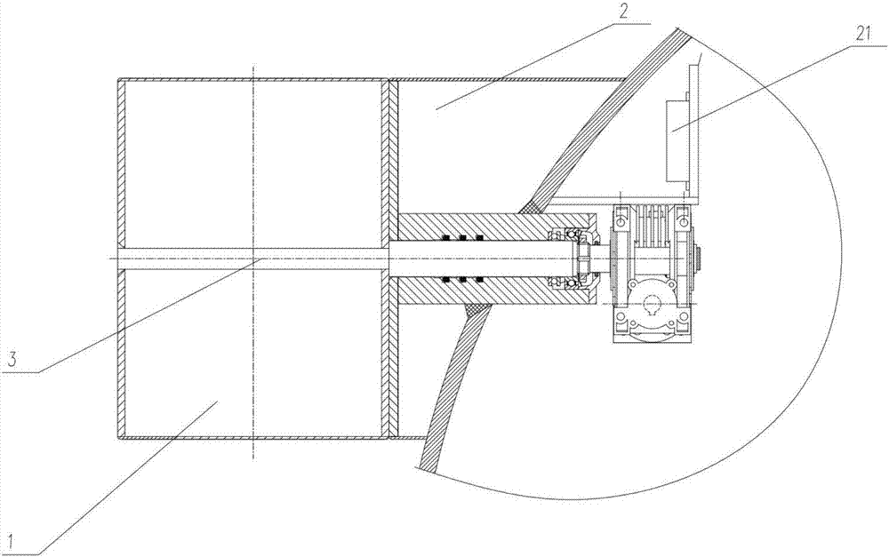
[0022] Such as figure 1 and figure 2 and image 3 A kind of elevating wing for submersible shown, comprises rotating wing 1, fixed wing 2, rotating shaft 3, axle sleeve 4, speed changer, and the speed changer of present embodiment is micro speed changer 19, also includes mounting base plate 17, stepper motor 20, stepper The motor driver 21, the fixed wing 2, the shaft sleeve 4 are fixedly connected with the submersible shell, the shaft sleeve 4 runs through the submersible shell, and the rotating shaft 3 is arranged on the shaft sleeve 4 through the thrust bearing 6 and the roller bearing 8 Inside, the thrust bearing 6, backing ring 7, roller bearing 8 and stop washer 9 are compressed sequentially through the round nut 10. One to three composite sealing rings 5 ​​are arranged between the shaft sleeve 4 and the rotating shaft 3 . In the...


PUM

PropertyMeasurementUnit
Angleaaaaaaaaaa

Abstract

The invention discloses a lifting wing for a submersible, comprising a rotating wing, a fixed wing, a rotating shaft, a shaft sleeve, a micro speed changer, a mounting bottom plate, a stepping motor and a stepping motor driver, wherein the fixed wing and the shaft sleeve are fixedly connected with a submersible shell; the shaft sleeve penetrates through the submersible shell; the rotating shaft is arranged in the shaft sleeve through a bearing; the outer end of the rotating shaft is connected with the rotating wing, and the inner end of the rotating shaft is connected with the stepping motor through the micro speed changer; and the micro speed changer and the stepping motor are fixed on the mounting bottom plate. The device can provide ascending force or descending force according to a positive or negative angle of attack of the lifting wing, so that the submersible can flexibly ascend or descend in water.

Description

technical field [0001] The invention belongs to the field of submersible devices, in particular to an elevating wing for a submersible. Background technique [0002] Underwater submersibles are an effective tool for human beings to explore, develop and play under the water bodies of oceans, lakes and reservoirs. The widespread application of underwater submersibles has important practical significance for exploring natural resources and national consumption. [0003] The current underwater submersible generally ascends and descends only by the drainage and water intake of the ballast tank, so the ascending and descending movement is not flexible enough. Contents of the invention [0004] In view of this, the object of the present invention is to provide an elevating wing for a submersible, which can use the positive or negative angle of attack of the elevating wing to provide a rising force or a descending force, so that the submersible can rise and fall flexibly in water...

Claims


Application Information

Patent Timeline
IPC IPC(8): B63G8/18
CPCB63G8/18
Inventor 沈家同刘建朝吴正光何良
Owner CHONGQING TONGLI INDAL
Why Eureka
Try Eureka