Light multi-rotor unmanned aerial vehicle frame carrier type take-off and landing platform

A multi-rotor unmanned, take-off and landing platform technology, applied in the direction of aircraft landers, etc., can solve the problems of difficult to find reliable take-off and landing points, difficulty in aircraft patrol operations, increased labor intensity, etc., to achieve convenient and fast loading and unloading, light weight, and labor-saving The effect of intensity reduction

Pending Publication Date: 2017-08-18
GUIZHOU POWER GRID CO LTD
View PDF10 Cites 1 Cited by
  • Summary
  • Abstract
  • Description
  • Claims
  • Application Information

AI Technical Summary

Problems solved by technology

However, Guizhou belongs to the karst landform, and its power grid transmission lines are mostly located on high mountains and ridges. Some pole towers have no vehicle roads. Operators need to carry drones to walk to the take-off and landing points that reach the effective working distance. In addition, they are packed in storage boxes. The weigh

Method used


Image

  • Light multi-rotor unmanned aerial vehicle frame carrier type take-off and landing platform
  • Light multi-rotor unmanned aerial vehicle frame carrier type take-off and landing platform
  • Light multi-rotor unmanned aerial vehicle frame carrier type take-off and landing platform

Examples


Embodiment

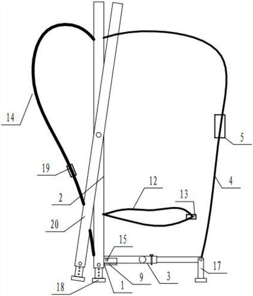
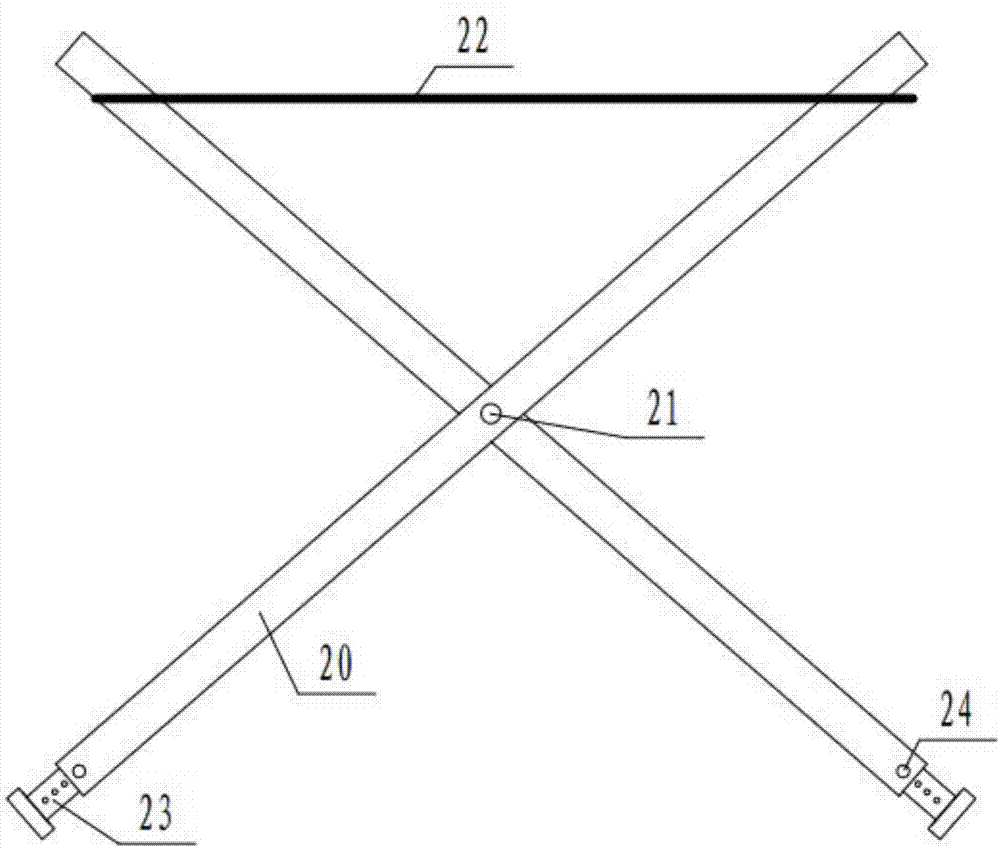
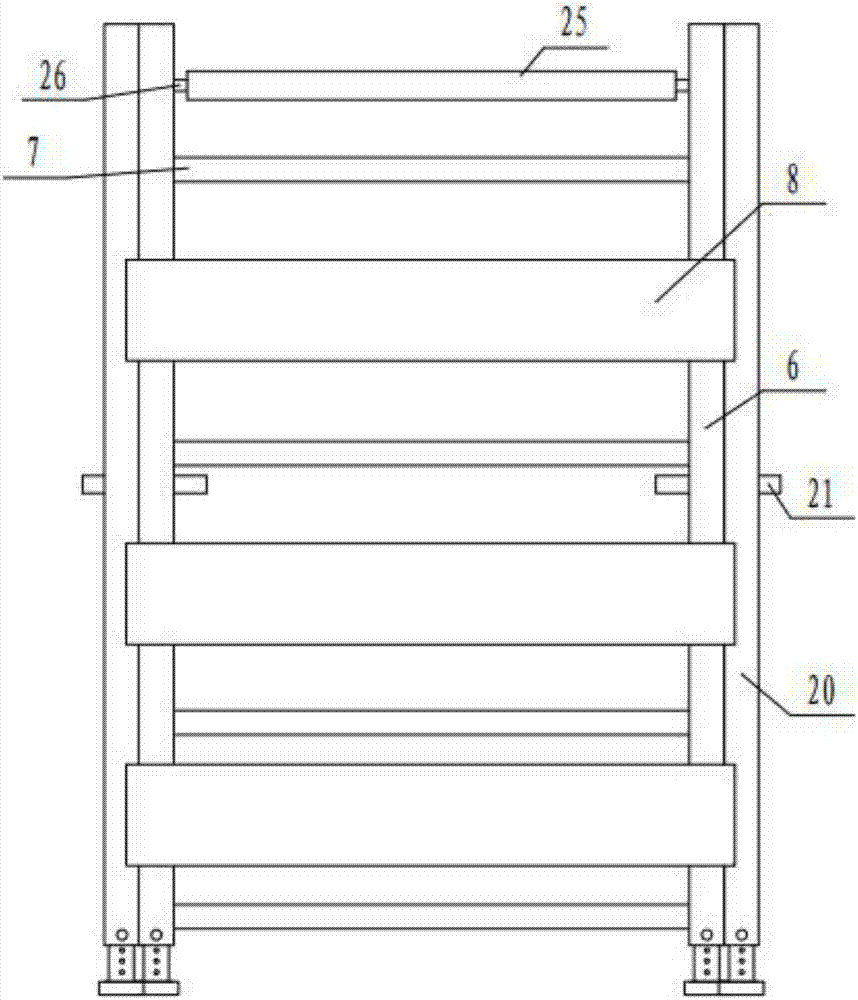
[0021] Example: such as Figure 1-Figure 5 As shown, a light multi-rotor unmanned aerial vehicle back-frame take-off and landing platform includes an L-shaped frame 1, the L-shaped frame 1 includes a front frame 2 and a bottom frame 3, the front end of the bottom frame 3 is connected to the lower end of the front frame 2, and the front frame 2 The front side is provided with double straps 14, and the rear end of the bottom frame 3 is fixedly connected with two wrapping straps 4, and the other end of the two wrapping straps 4 is connected to the upper end of the front frame 2 after bypassing the drone. Symmetrically rotatable two rotating rods 20 of equal height, the two rotating rods 20 rotate around the rotating shaft 21 and intersect with the front frame frame 2, and a detachable fabric made of high-strength fabric is arranged on the front frame 2 upper end and the two rotating rods 20 upper ends. The canvas 22 and the double straps 14 are provided with a strap lock 19, the ...


PUM


Abstract

The invention discloses a light multi-rotor unmanned aerial vehicle frame carrier type take-off and landing platform which comprises an L-shaped framework; the L-shaped framework comprises a front framework and a bottom framework; the front end of the bottom framework is connected to the lower end of the front framework; two shoulder straps are arranged at the front side of the front framework; the rear end of the bottom framework is fixedly connected with two wrapping tapes, and the other ends of the two wrapping tapes bypass an unmanned aerial vehicle and then are connected to the upper end of the front framework; two rotating rods which are symmetrical and rotatable and have the same height with the front framework are arranged at two sides of the front framework; the two rotating rods rotate around a rotating shaft and then are crossed with the front framework; and a detachable canvas made of high-strength fabrics is arranged at the upper end of the front framework and the upper ends of the two rotating rods. The platform disclosed by the invention can realize back carrying of the unmanned aerial vehicle and can serve as a lifting platform, the carrying of the unmanned aerial vehicle is more time-saving and labor-saving, the labor intensity is greatly reduced, and the structure is more compact; the platform is more convenient to carry when a user walks in karst topography; and the canvas is adopted for lapping the platform, the purpose of the lifting platform of the unmanned aerial vehicle is realized, the functionality of the frame carrier is greatly improved, and the utilization ratio is higher.

Description

technical field [0001] The invention relates to a light-duty multi-rotor unmanned aerial vehicle back-frame take-off and landing platform, which belongs to the technical field of electric inspection unmanned aerial vehicle handling and lifting devices. Background technique [0002] In response to the China Southern Power Grid's "13th Five-Year Plan" aircraft inspection + human inspection cooperation plan, Guizhou Power Grid has planned the differentiated inspection configuration of transmission lines during the "13th Five-Year Plan" period, and drone inspections will become the main method of transmission line inspections. However, Guizhou belongs to the karst landform, and its power grid transmission lines are mostly located on high mountains and ridges. Some pole towers have no vehicle roads. Operators need to carry drones to walk to the take-off and landing points that reach the effective working distance. In addition, they are packed in storage boxes. The weight is incre...

Claims


Application Information

Patent Timeline
IPC IPC(8): B64D45/06
CPCB64D45/06
Inventor 陈科羽
Owner GUIZHOU POWER GRID CO LTD
Why Eureka
Try Eureka