Internal stirring structure of sludge hydrolysis tank

A hydrolysis tank and internal stirring technology, which is applied in the direction of mixer accessories, pyrolysis treatment sludge, mixer with rotating stirring device, etc., can solve the problems of small sludge flow, low hydrolysis efficiency, no gap, poor fluidity, etc. Achieve the effect of promoting sludge hydrolysis, high hydrolysis efficiency, and strong stirring

Pending Publication Date: 2017-08-18
SICHUAN GAOBO ENVIRONMENTAL PROTECTION ENG CO LTD
View PDF17 Cites 3 Cited by
  • Summary
  • Abstract
  • Description
  • Claims
  • Application Information

AI Technical Summary

Problems solved by technology

[0004] Due to the large heat capacity of the sludge itself, no gaps, and poor fluidity, the thermal conductivity is also poor. In the process of sludge hydrolysis and heating, the existing sludge hydrolysis equipment has little flow due to insufficient agitation. Insufficient and uneven heat transfer results in inefficient hydrolysis

Method used


Image

  • Internal stirring structure of sludge hydrolysis tank
  • Internal stirring structure of sludge hydrolysis tank
  • Internal stirring structure of sludge hydrolysis tank

Examples


Embodiment Construction

[0018] The present invention will be further described below in conjunction with accompanying drawing, protection scope of the present invention is not limited to the following:

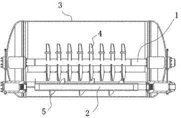
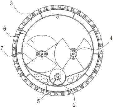
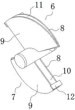
[0019] like Figure 1~Figure 3 As shown, the stirring structure in the sludge hydrolysis tank includes two main stirring shafts 1 and a spiral stirring and discharging shaft 2. The two main stirring shafts 1 and the spiral stirring and discharging shaft 2 are connected to corresponding motors respectively. The root main stirring shaft 1 is arranged in the middle part of the vertical direction of the hydrolysis tank 3, and the two main stirring shafts 1 are arranged side by side. The main stirring shaft 1 is provided with multiple groups of alternating stirring blades 4, and the stirring blades 4 play the role of stirring the sludge. function, so that the cell membrane or cell wall of sludge aggregated organic matter is broken, which is convenient for the anaerobic reaction of anaerobic bacteria, and ...


PUM


Abstract

The invention discloses an internal stirring structure of a sludge hydrolysis tank. The internal stirring structure of the sludge hydrolysis tank comprises two main stirring shafts and a spiral stirring and discharging shaft, wherein the two main stirring shafts are arranged in the middle of a vertical direction of the hydrolysis tank side by side; a plurality of groups of stirring blades is arranged on each main stirring shaft; the spiral stirring and discharging shaft is arranged at the bottom of the hydrolysis tank; auger blades are arranged on the spiral stirring and discharging shaft, and the stirring direction of the auger blades is opposite to that of the stirring blades; the two main stirring shafts and the spiral stirring and discharging shaft are all hollow shafts; the stirring blades and the auger blades are all hollow blades, and the main stirring shaft is communicated with the stirring blades; the spiral stirring and discharging shaft is communicated with the auger blades. The internal stirring structure of the sludge hydrolysis tank has the beneficial effects of good stirring effect, sludge circulation flow and good sludge fluidity.

Description

technical field [0001] The invention relates to the technical field of sewage treatment, in particular to a stirring structure in a sludge hydrolysis tank. Background technique [0002] With the acceleration of industrialization and urbanization in our country, the domestic sewage production and sewage treatment capacity are growing rapidly, and the sludge production is also growing rapidly. As a misplaced resource, sludge will cause serious secondary pollution to the environment if it is not properly treated. With the continuous deterioration of the environment, the increasing shortage of land use and the enhancement of people's awareness of environmental protection, effective treatment of sludge has gradually been put on the agenda. [0003] Sludge is the product of sewage treatment, including organic residues, bacterial colonies, and inorganic particles. Sludge has a high water content and is a thick medium between solid and liquid. It is difficult to achieve the purpos...

Claims


Application Information

Patent Timeline
Patent Type & Authority Applications(China)
IPC IPC(8): C02F11/10B01F15/06B01F7/02
CPCC02F11/10B01F27/2322B01F27/60B01F27/191B01F35/95B01F2035/99
Inventor 陈凌霄张捷
Owner SICHUAN GAOBO ENVIRONMENTAL PROTECTION ENG CO LTD
Why Eureka
Try Eureka